December 23, 2025
How to Create a Digital Terrain Model
Global Mapper 27 is here. Geodetic accuracy, built into every workflow.
In the geospatial industry, acronyms like DEM, DSM, and DTM are frequently used when referring to elevation data, but they aren’t interchangeable. A Digital Elevation Model (DEM) is a general term for a raster representation of elevation values, most often referring to a bare-earth surface. A Digital Surface Model (DSM) represents the top of the Earth’s surface, including buildings, vegetation, and other above-ground features. A Digital Terrain Model (DTM) specifically represents the underlying ground surface, with structures and vegetation removed.
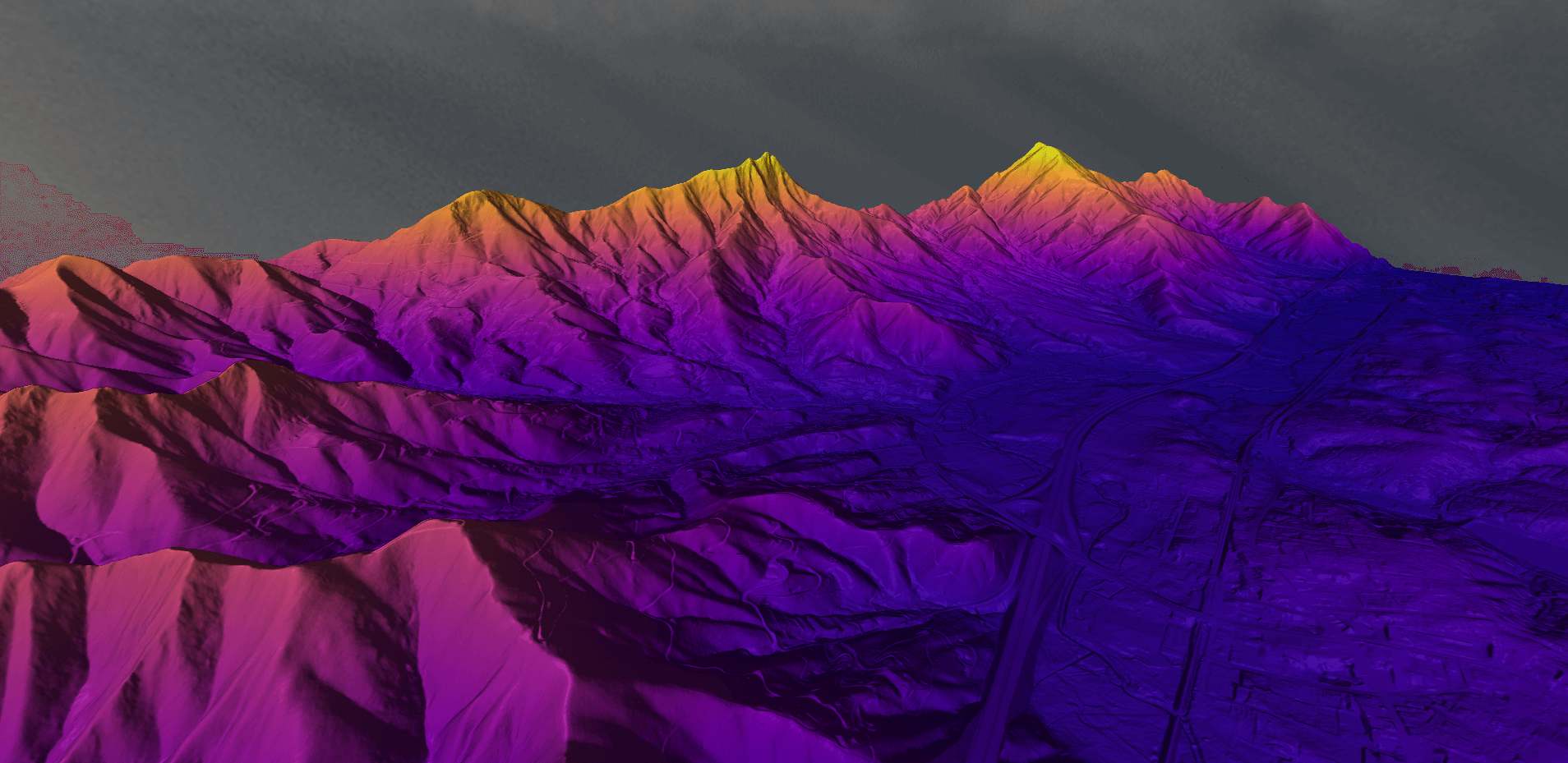
Digital Terrain Models are essential for analyses such as hydrology modeling, slope and contour generation, earthwork calculations, and any workflow where an accurate representation of the true ground surface is required. In the sections that follow, we’ll walk through how to create a DTM in Global Mapper®, including optimizing parameters, choosing gridding methods, and applying best practices for point cloud–based modeling.
The Elevation Grid Creation tool in Global Mapper uses any 3D vector data to generate a gridded raster elevation layer, including digital terrain models. DTMs can be made in just a few steps: load your elevation data, open the Create Elevation Grid tool, choose a binning method, and click OK. Once created, terrain models can be visualized, edited, analyzed, and exported in one of the many supported elevation formats– all within Global Mapper.
In practice, DTMs are commonly derived from lidar or other 3D data sources by isolating ground measurements and interpolating them into a continuous surface. When creating a DTM from a point cloud, it’s best to first classify the ground using Global Mapper Pro’s point cloud classification tools. Available within the Point Cloud Analysis tool, the ground classification process automatically identifies and labels likely ground points. When generating the elevation grid, you can then filter by classification to exclude non-ground points, ensuring the resulting surface accurately represents the terrain.


When creating an elevation grid, the Create Elevation Grid dialog offers multiple methods for interpolating 3D vector data into a continuous surface. The two primary approaches are Triangulated Irregular Network (TIN) and Binning methods. Understanding how each method works will help you choose the best option for your data and analysis goals.
The image below provides a visual comparison of elevation grids generated from the same data using different methods, shown along a common path in the Path Profile tool. In this example, the binning method produces a smoother surface than the triangulated method. While both approaches are widely used, binning is the more popular choice overall. There is ongoing debate within the industry about which method offers higher accuracy, but the answer largely depends on how accuracy is defined and how the resulting surface will be used. Ultimately, the best method is the one that meets the needs of your specific project.

The Triangulated Irregular Network (TIN) method is well-suited for users who want a surface that closely follows key or significant points in the source data. Using this approach, Global Mapper connects 3D point features, including vertices from 3D line and area features, into a network of triangles. The software then interpolates elevation values across the triangular faces using the feature elevations and slope information to generate a gridded elevation layer that emulates a TIN surface. Additionally, Global Mapper can auto-flag Model Key Points for use in creating a simplified surface well-suited for the TIN process. The vector TIN surface can be saved as well, for easy export to your choice of CAD software.

Global Mapper Pro includes several variations of the binning method, including Average, Minimum, and Maximum value. Binning is particularly well-suited for point cloud–based workflows, as it does not rely on every individual point when generating the output grid. Instead, representative points are selected based on their elevation characteristics within defined areas.

The binning method works by spatially dividing the dataset into bins that correspond to the resolution of the output grid cells. A single elevation value from each bin is then used to represent the corresponding cell in the final gridded layer. The value chosen depends on the selected binning method—for example, Binning Minimum Value uses the lowest elevation within each bin, making it especially useful for generating bare-earth terrain models from lidar data.
Once a terrain surface has been generated, you may notice areas that benefit from additional cleanup or refinement—particularly where point cloud data is incomplete or inconsistent. Water bodies such as ponds, lakes, and rivers often produce inconsistent returns, which can introduce noise into an elevation grid. When a terrain model includes water-covered areas, it’s often helpful to flatten those regions to a uniform elevation value.
This can be achieved by creating a 3D area feature that matches the size of the water body, and including it in the grid creation process. Enabling the option to Use 3D Area/Line Features as Breaklines will “burn” the feature’s elevation into the output grid, effectively flattening elevation variation within the defined area. This same approach can also be applied to roads, building footprints, or any area where a uniform elevation is desired. If additional refinement is needed after the grid is generated, the Terrain Painting tool can be used to manually edit and smooth the surface.

With a finalized elevation grid, you can extend your analysis in Global Mapper—create contour lines, map watersheds, calculate volumes, and perform a wide range of terrain-based analyses. Explore additional workflows and tips in the Video Collection page.
Try generating a digital terrain model in Global Mapper Pro today with a free 14-day trial! If you have any questions, please contact us!
Explore more terrain analysis tools Global Mapper has to offer: