 Performing Raster Transforms
To create a new Transform job, you can select 'Raster Transform from the Start Page and 'Create Job' or:
- Right-click in the Project Manager and select Create New Job>Raster Transform
- Go to File>New> Job >Raster Transform
- Click on the button
on the tool bar.
Raster Transform Job Settings
The settings for a transform job are broken into sections. To properly set up a Raster Transform job, all settings must be filled in. Follow the steps below to set up a Transform job.
Input Settings
![]()
-
In the Image File field specify the image to be transformed by clicking the Browse(...) button and browse to and select the file. Once specified, a thumbnail of the image will display in the upper right corner of the Transform job panel.
-
In the Reference File field, specify the file containing the georeference data for the image you selected in the Image File field. Supported reference formats include:
- Blue Marble (*.rsf))
- HDR Reference Files (*.hdr)
- DOQQ (*.doq)
- World files (various file extensions)
- MapInfo Raster (*.tab)
- ECW Reference File (*.ers)
- Internal Referencing (GeoTIFF, ECW, JP2, CADRG, ADRG, DOQQ, etc.) If the file is internally referenced, the Reference File field will automatically populate with the name of the Input File.
If the Image File does not yet have a Reference File, you will need to Georeference the image prior to transformation.
-
The Transform Model for the georeference data will be used to calculate the geographic location of each pixel in the image according to various mathematical models. The more complex a model you choose, the more control points will be required in the reference file. If you are using an image that has already been georeferenced and transformed to a known system, Affine should be used. Supported models are:
Coordinate Systems and Datum Transformation
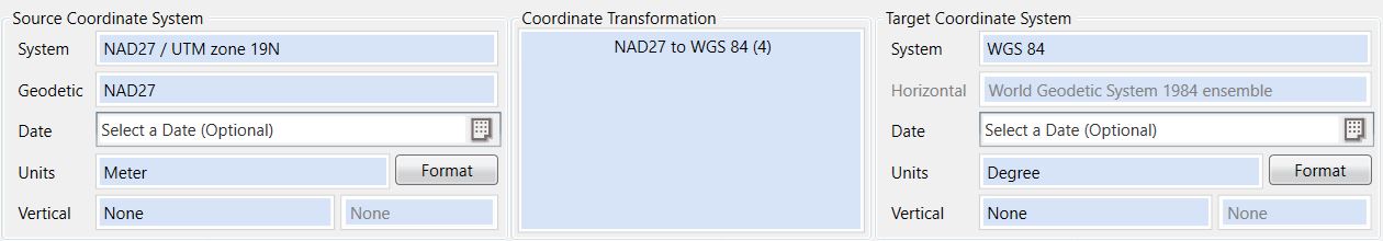
-
The Reference Coordinate System is the coordinate system used to georeference the image. If you loaded an image Reference File that contains a coordinate system definition, such as RSF, TAB, GeoTIFF, JP2, and ECW, then the Reference Coordinate System should be set automatically for you. If your reference file does not automatically select the coordinate system, you may set the system manually. Please see: Selecting a Coordinate System
Note: World Files (TFW, JGW, SDW, etc) do not contain any coordinate system information and must have their coordinate system selected manually.
-
Select the Destination Coordinate System for the output image.
-
If necessary, Select a Coordinate Transformation to choose the appropriate transformation between the Reference and Destination Datums.
Output Settings
![]()
-
The Destination File is the output file that will be created from the transformation. Use the Browse(...) button to open the Select Destination File dialog that will allow you to choose an output location, an output format for the new image, and a name for the file.
-
If you are transforming to a geodetic coordinate system, you will need to specify a Central Latitude for the output image. Central Latitude is used to calculate the pixel scale value for the output image. There are three options for specifying the central latitude of the image:
- Input Image: The central latitude is set to the latitude at the center of the input image. The Input image must be referenced with a geodetic coordinate system.
- Transform Area: The central latitude is set to the latitude at the center of the transformation area. This will differ from the Input Image if you set a transform area different from the image extents.
- User Specified: This allows for manual entry of the latitude in the text box.
-
Pixel Resolution is the ground distance covered in an image by each pixel. This can be auto-calculated by using the check box, or manually specified by disabling the checkbox and entering your desired resolution.
-
The Set Transform Area button can be used to transform a sub area of the whole input image allowing you to crop the image.
-
The Preferences button allows you to select output reference file types, resampling methods, compression options, and processing strip size.
-
Once all settings are in place, you can click the Transform button at the bottom of the Job panel to start the process. While the job processes, you will see a progress meter in the Project Manager window and relevant messages in the Messages window.
-
You may click the Metadata button to view and edit Metadata for this file.