DEM Digital Elevation Models. This is data stored in a pixel-based raster format, where the pixel value represents elevation. Transformations
Supported input formats:
-
USGS ASCII DEM (*.dem)
-
BIL Raster Dataset (*.bil) (This file type could contain either two-dimensional or three-dimensional data.)
-
BSQ (*.bsq) (This file type could contain either two-dimensional or three-dimensional data.)
Supported DEM output formats:
-
Arc/Info ASCII Grid (*.asc)
-
USGS ASCII DEM (*.dem)
DEM files can also be written out as two-dimensional raster images in any of the supported raster output file types. Converting a three dimensional image to a two dimensional raster will create a file with two-dimensional coordinate referencing and colors based on the DEM shader options.
Setting up a DEM Transformation is similar to setting up a transformation. In addition to converting from one horizontal coordinate system to another, you can also convert from one vertical system to another. Double-click in the Vertical box in the Reference Coordinate System area to select the vertical reference for your input data. Double-click in the Vertical box in the Destination Coordinate System area to select a vertical reference for your output data. If you do not wish to convert the vertical values, you can leave both vertical references set to None.
Elevation Shader
Loading a DEM file into the Transform job will enable the Configure Shader button, which opens the Configure Elevation Shader dialog. This dialog can also be accessed when you load a DEM file in the viewer, or by selecting Options>Preferences, opening the Viewer tab, and clicking the Configure button to the right of Default DEM Shader. The Elevation Shader controls how DEM files appear in the Geographic Calculator Viewer, and how they will be written if your output file type is a standard, two-dimensional raster file.
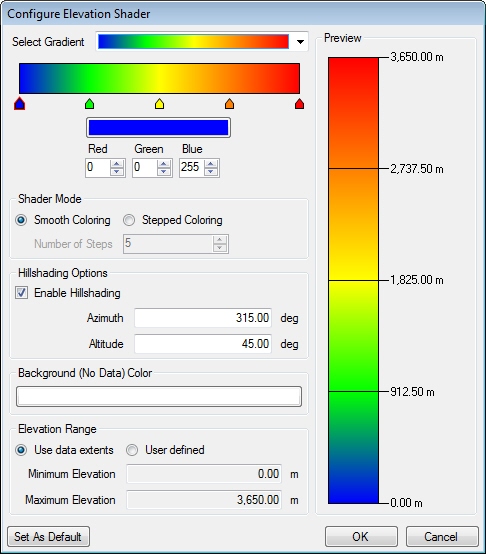
The Select Gradient dropdown list includes several ready-made gradient options. The gradient bar below that dropdown box allows you to create your own gradient. Right-clicking in the gradient will activate a context menu that allows you to reset or reverse the gradient or to set equal spacing between steps.
Each arrow represents a color step. Clicking the arrow will highlight that step. Change the color of the highlighted step by clicking in the color bar below or by entering red green blue values. Move the step to a higher or lower vertical value by dragging the arrow to the right or left. Remove a step by right-clicking the arrow and selecting Remove, or add a step by clicking below the gradient.
In the Shader Mode area, you can select either smooth coloring, which gives gradual color changes, or Stepped Coloring. Selecting Stepped Coloring will activate the Number of Steps options.
Hillshading Options control the shading of DEM files. You can disable the shading to view elevations with only the color gradient. The azimuth and altitude represent the direction and height of the sun. Azimuth is measured in degrees clockwise from north and altitude is measured in degrees up from the horizon.
The Background (No Data) Color is used only for pixels in the DEM that contain no height value.
Elevation Range is defaulted to the extents of the vertical data, but can be adjusted to user specified elevations.
Clicking the Set As Default button in either a Transform job or Viewer Elevation Shader Dialog will set the selected shading options as a default for new Transform jobs and for the Viewer.