 Vectorize Raster
The Vectorize Raster tool creates area features from raster images based on a chosen pixel color, elevation layers based on a height range, or elevation layers based on slope values.
The shader applied to the layer being operated on will determine whether elevation, slope, or slope direction values are being considered in the vectorization process. Change the shader (link) to slope or slope direction to vectorize the elevation layer based on slope values. Slope can be measured by degrees or percentages.
To open this tool, select  this button from the Digitizer Toolset. This tool is also available from the Layer menu, or by right clicking on an image or elevation layer in the Control Center and choosing Vectorize Raster in the Layer sub menu.
|
|
This tool requires Global Mapper Pro |
1. Select the Vectorize Raster button from the Advanced Digitizer toolbar, or right click on your desired raster layer in the Control Center.
2. Choose which layer you would like to work on then click OK.
3. Choose a color using the color box selection or enter an elevation range or slope range.
4. Enter additional settings such as Smooth Area Times and Simplify.
5. Click OK.
6. A resulting area feature layer should be created based on the settings chosen.
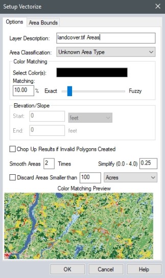
Options
Layer Description defines the resulting layer name.
Area Classification drop down allows you to choose the Area Type for the resulting layer.
Color Matching
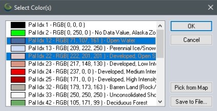
Click the color box next to Select Colors(s) to open a color picker or a list of available palette colors values if available from the image layer. If the layer is an elevation layer, this section will be disabled for selection. Use Control key on keyboard to select multiple colors at the same time. Values will populate with palette names or classifications if they are available in the image. Pick From Map opens an eye dropper tool whichs allows you to pick a color on the actual image in the workspace. Save To File allows you to save a palette file (.pal) of the chosen RGB values.
Matching slider section specifies how to group RGB values into area features. Based on the 8-bit color range of values, specify the percent range of shades to include above and below the given color value.
Elevation/Slope/Slope Direction
The shader applied to the layer being operated on will determine whether elevation, slope, or slope direction values are being considered in the vectorization process. Change the shader (link) to slope or slope direction to vectorize the elevation layer based on slope values. Slope can be measured by degrees or percentages.
Enter a Start value and End value to determine a range of elevation/slope/slope direction values to generate area features.
Additional Options
Smooth Area allows you to enter a value to adjust the appearance of the generated area features. Lower values will create features with more jagged edges while higher values will create features with smoother edges. Adjusting the value of the Smooth Area and running the Vectorize Raster tool with all other settings the same will create vertices of the generated area features in slightly different locations.
Simplify allows the user to set up the threshold at which points that do not contribute much to the shape of the generated area features are removed in order to generate areas with less vertices. A greater simplify value will increase simplification. Valid values are between 0 and 4 with 0 performing no simplification.
Discard Areas Smaller than sets minimum area for features to be kept. Enter an area and area unit and all features with an area smaller will be discarded.
Area Bounds
Examples
Palette Image
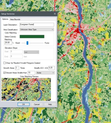
This image is set to create area features from the dark green pixels in the landcover image. The pixel color was chosen from the Select Colors color box using the available color palette from the image file. The pixel color matching slider is set to 25%, Smooth Areas 2 Times is entered and Simplify Value of 0.25 is set. The check box to discard area features smaller than 10 acres is enabled.
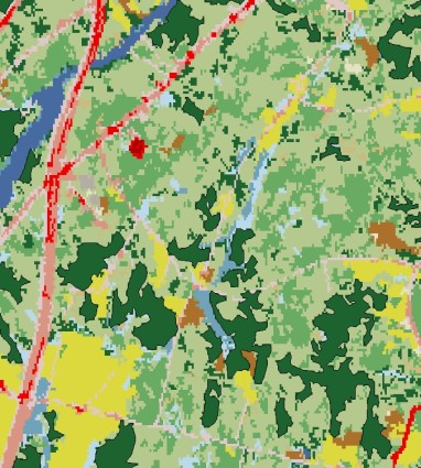
The result is area features tracing the pixel values that matched the color criteria. This initial result can be improved through further digitizer tools to reshape and combine the areas. Suggested further steps include using Simplify and Smooth tools to reshape the feature.
Height Values from Elevation Layer
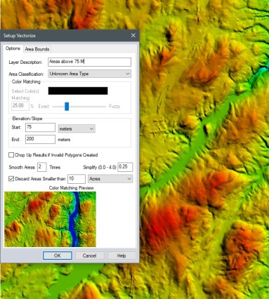
This image is set to create area features between the range for 75 to 200 meters from the elevation layer. Note that the color picker is disabled. Smooth Areas 2 Times is entered and Simplify Value of 0.25 is set. The check box to discard area features smaller than 10 acres is enabled.
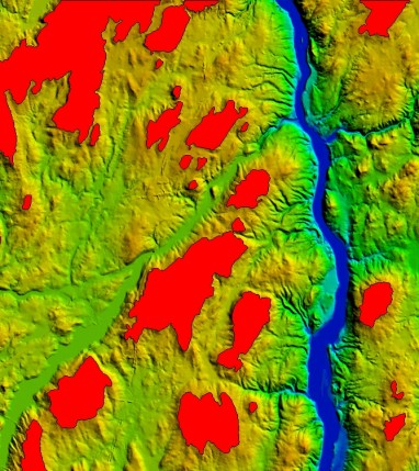
The result is red area features tracing the pixel height values between 75 and 200 meters. This initial result can be improved through further digitizer tools to reshape and combine the areas. Suggested further steps include using Simplify and Smooth tools to reshape the feature.
Slope Values from Elevation Layer
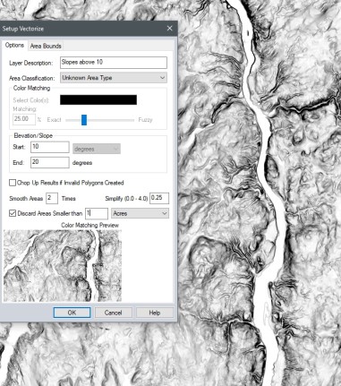
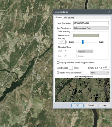
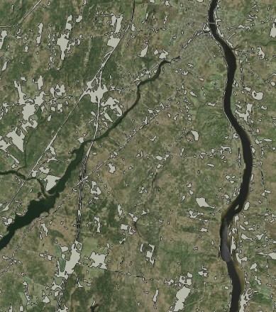
Slope Shader or a custom shader based on slope degrees must be set as he shader mode to use the Vectorize Raster tool for slope values. This image is set to create area features between the slope range of 10 to 20 degrees from the elevation layer. Note that the color picker is disabled. Smooth Areas 2 Times is entered and Simplify Value of 0.25 is set. The check box to discard area features smaller than 1 acre is enabled.
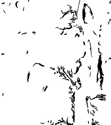
The elevation layer was turned off for this picture. The result is black area features tracing the pixel slope values between 10 and 20 degrees.This initial result can be improved through further digitizer tools to reshape and combine the areas. Suggested further steps include using Simplify and Smooth tools to reshape the feature.
Imagery
This image is set to create gray area features. The color was picked using Pick from Map option since this image did not have an associated palette file. Smooth Areas 2 Times is entered and Simplify Value of 0.25 is set. The check box to discard area features smaller than 1 acre is enabled.
This initial result can be improved through further digitizer tools to reshape and combine the areas. Suggested further steps include using Simplify and Smooth tools to reshape the feature.