Strip / Flight Line Alignment
Use the Lidar Strip Alignment tool to easily adjust one lidar strip / flight line to match another through the manual placement of control points. This tool is similar to Lidar QC, but is tailored for aligning strips / flight lines.
Find the Strip / Flight Line Alignment tool in the Lidar Analysis menu under Lidar QC.
This tool requires flight lines to be previously established. If the flight lines are not separated by layers or labeled in an attribute, click the Calculate Flight Lines… button to open the Find Flight Lines (Swaths) tool to identify the flight lines and assign a flight number to a USER_DATA or SOURCE_ID attribute.
Related tools:
Find Flight Lines (Swaths) - Identify separate flight lines in lidar data based on GPS time.
Create Swath Separation Image - Create a raster used as a quality assessment of vertical alignment of collected lidar swaths.
Setup Strip Alignment
Choose which layers will be listed as options to be included in the alignment and how the flight lines are distinguished.
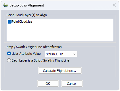
Point Cloud Layer(s) to Align - Choose all clouds that are to be aligned. While only two strips can be compared at a time, all selected layers will be available to switch between and adjust.
Strip / Swath / Flight Line Identification
-
Lidar Attribute Value - If multiple strips are contained within the same layer, choose this option and select the attribute that represents the strip number.
-
Each Layer is a strip Flightline - Choose this option to treat each layer as an individual flight line.
Calculate Flight Lines can be used (if needed) to create an attribute to separate flight lines.
Click OK to proceed to the Lidar strip Alignment tool
Lidar Strip Alignment
Quick Steps for using the Lidar Strip Alignment tool
- Select the Strips to Align - Choose which strip is to be adjusted and which strip is to be used as the reference for that adjustment.
- The “From” strip will be aligned to the “To” strip.
- Specify an alignment method.
- If using Best Fit or Affine, use the Associated Lidar Positions from Strips tool to specify control points.
- Place Alignment Points (see additional steps below).
- Click Fit Lidar to Control Points to perform the alignment.
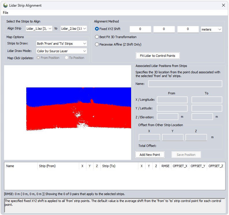
Select the Strips to Align
Choose which strip is to be adjusted and which strip is to be used as part of the basis for that adjustment. The “From” strip will be aligned to the “To” strip.
Use File > Load Control Points from File to import ground control points from a file if you have previously exported them as .gm_strip_align files.
Map Options
These settings pertain to the data viewer within the dialog.
Strips to Draw - Choose which strips appear in the map viewer.
All Strips - Displays all point clouds that were checked in the Setup Strip Alignment dialog (and are available in the From/To dropdowns).
Both ‘From’ and ‘To’ Strips - Displays both "From" and "To" clouds at the same time.
Only ‘From’ or ‘To’ for Map Click -Shows the ‘From’ point cloud until a point is placed, then automatically turns off the "From" cloud and turns on the "To" cloud to allow easy placement of the next point.
Lidar Draw Mode - Select which attribute to color the point clouds by. Color by Source Layer is useful for distinguishing multiple point clouds based on layer. Use Colors if Present will display RBG values (if available), etc.
Map Click Updates - Choose which coordinate values are being updated.
Alignment Method
Fixed XYZ Shift - The specified fixed XYZ shift is applied to all “From” strip points. The default value is the average shift from the “From” to “To” strip control point for each control point.
Best Fit 3D Transformation - A best-fit 3D transform is calculated from each enabled “Ffrom” strip point to the associated “To” strip 3D location. The “From” strip points are the adjusted using the calculated transformation. If only Z values are adjusted, a best-fit plane adjustment is done. See How to Place Alignment Points below.
Piecewise Affine (Z Shift Only) - A piecewise-affine (triangulation) transform results in an exact Z shift at each “From” strip point, and an interpolated result in between, trailing off to zero far outside the points. See How to Place Alignment Points below.
Associated Lidar Positions from Strips
Steps for Placing Alignment Points
The goal is to identify locations (coordinates) in each point cloud that reference the same point in space. Remember that the From cloud is going to be adjusted to match the position of the To cloud based on these points and through the chosen Alignment Method.
- Click Add New Point
- This turns on the coordinate options. You can manually type in the coordinates if you have that information on hand, or use the built-in Map viewer to choose points to base the alignments on.
- Name the Point feature.
- Click within the map viewer to place control points.
- Use the Map Click Updates toggle to determine if the points you are placing in the map correspond to the From cloud or the To cloud.
- It will toggle automatically as points are placed.
- Optional: Change the Lidar Draw Mode to better visualize the features you are looking to identify in the cloud. Intensity and RGB are useful for this.
- Offset from Other Strip Location will automatically show the distance between the current From and To control points for your reference.
- Total Offset measures the 3D distance between the From and To points, or the magnitude of the vector from the XYZ offsets.
- Use the Map Click Updates toggle to determine if the points you are placing in the map correspond to the From cloud or the To cloud.
- Click Add New Pointagain to save this control point, and create the next point.
- Points are populated in the table at the bottom of the dialog. Click on a point to view it for editing, or uncheck it to omit it from the Alignment process.
- Once enough control points have been specified, click Fit Lidar to Control Points to perform the alignment.