 Lidar QC tool: Compare/Adjust Point Cloud to Control Points
The Lidar QC tool compares control points to nearby Lidar points for location accuracy measurements and optional point cloud adjustment. The tool can also calculate several types of vertical or 3D adjustments and fit the point cloud to the control points if desired.
Elevation/Vertical QC - this is the default functionality of the tool. Control points are compared against nearby points in the point cloud layer to measure the elevation difference between the two. See "Point Cloud Elevation Calculation Setup" in the first dialog below.
Horizontal QC - this function requires additional input from the user. The data viewer is used to manually specify the locations in the point cloud that correspond to each control point. See "Associated Lidar Position" in the second dialog for more information.
|
|
This tool requires Global Mapper Pro |
Compare Lidar to Control Points
The first dialog specifies which data layers to use.
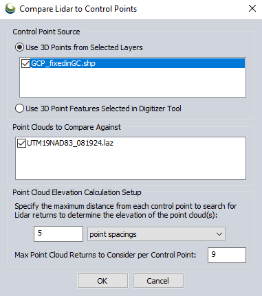
Control Point Source
Use 3D Points from Selected Layers- Specify the layer that contains the control points.
Use 3D Point Features Selected in Digitizer Tool - Select this option to only compare to pre-selected control points.
Point Clouds to Compare Against
Select which point cloud layers are to be compared and optionally adjusted.
Point Cloud Elevation Calculation Setup
Maximum distance - The furthest horizontal distance at which Global Mapper will search for lidar points near each control points. The default search distance is 5 point spacings, with a minimum nearby distance of .25 meters and a maximum of 5 meters.
Max Point Cloud Returns to Consider per Control Point -The default value is 9. These points are used to calculate the difference between the control points and the point cloud, stopping the search after finding the max number of point cloud returns closest to each point. The actual number of points found and used (within your Maximum Distance) will be displayed in the report under LIDAR_POINT_COUNT.
The calculation uses Inverse Distance Weighting (IDW) of the control points to calculate the expected Z value of the nearby lidar points; points in the cloud that are closer to the control have a greater influence on the calculated LIDAR_ELEV used for comparison against the corresponding control point elevation.
Lidar Control Point Match Information
The Lidar Control Point Match Information dialog provides offset statistics for each control point, options for vertical positional adjustment of the point cloud, and the option to tag the horizontal location of control point targets in the point cloud to add horizontal offset statistics and unlock 3D adjustment options.
- The viewer is used to manually assign an Associated Lidar Position for the currently selected control point.
- The checkbox next to each control point controls whether or not the point will be used to calculate the fit to be applied to the point cloud.
Settings:
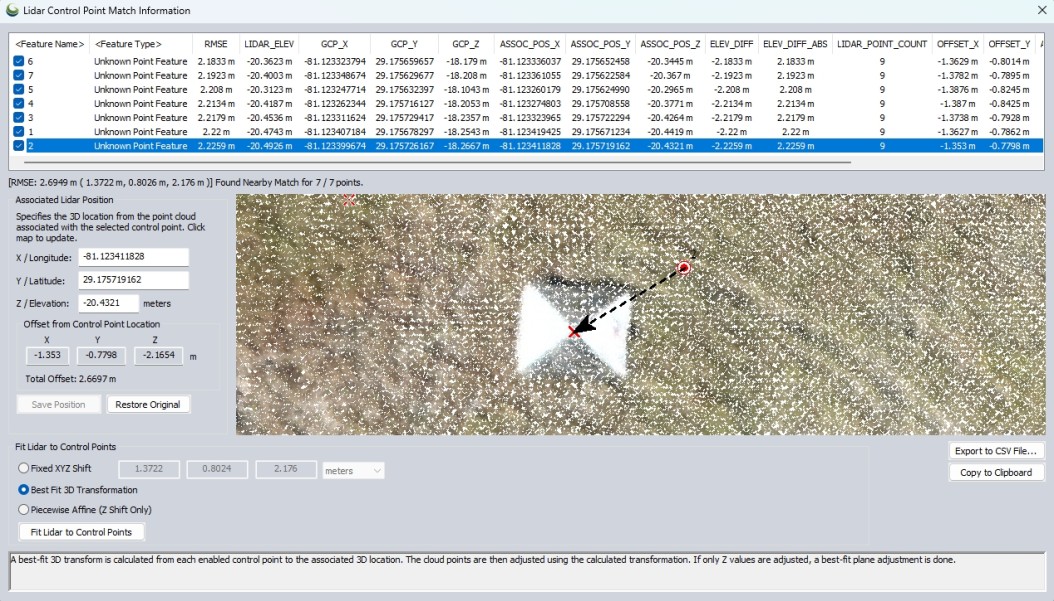
Data table
The data table displays a list of the input control points and offset values from corresponding location in the point cloud. The calculated statistics will not include lidar points that are hidden due to your lidar filter settings.
When the dialog first opens, only vertical offset is shown, as it is calculated automatically. As you tag the horizontal location of each control point in the point cloud, the table updates to show X and Y offset.
Uncheck individual control points to exclude them from the RMSE statistics display and adjustment calculations.
Attributes and Statistics
RMSE - The root mean square error is a measure of the difference between the expected elevation from the control points and the measured lidar values.
LIDAR_ELEV - Elevation of the point cloud as determined by user input in the previous Point Cloud Elevation Calculation Setup dialog.
ELEV_DIFF_ABS - Absolute elevation difference between the point cloud and control point (reported in the native unit of the control points).
ELEV_DIFF - Elevation difference between the point cloud and control point (reported in the native unit of the control points). Negative values indicate the point cloud is lower than the control point.
LIDAR_POINT_COUNT - The number of nearby lidar points being compared to the control point. This is the number found within the maximum distance, capped at the Max Point Cloud Returns to Consider set in the initial Point Cloud Elevation Calculation Setup dialog.
ASSOC_POS_X and ASSOC_POS_Y - When horizontal locations of the control have been tagged in the point cloud, these attributes record the updated point cloud location information specified in the data viewer. These values are also visible in the XYZ values in the Associated Lidar Position section of the dialog.
OFFSET_X and OFFSET_Y - When horizontal locations of the control have been associated in the point cloud, offset from control point (GCP) X an Y coordinates is reported here.
Overall RMSE is reported at the bottom of the dialog.
Found Nearby Match indicates the number of control points that had nearby Lidar points for comparison.
Associated Lidar Position
By default, for vertical rectification, each control point has already been compared to the point cloud elevation using the Point Cloud Elevation Calculation Setup settings specified in the previous dialog. If no horizontal offset exists, you may proceed to applying any of the vertical adjustment options only, as these are automatically calculated.
However, if any horizontal offset exists, you will need to manually tag the control point locations in the point cloud to generate the horizontal offset report and optionally apply a 3D rectification.
For Global Mapper to calculate and perform a 3D adjustment, you must manually associate each control point with its corresponding location in the point cloud.
Quick Steps to associate lidar position with a control point:
Use the data viewer to associate a control point with a specific location in the point cloud:
- In the data table, select a control point to automatically zoom to it in the data viewer. The control points are represented in the viewer with a target icon.
- Click in the viewer to manually specify the corresponding location in the point cloud.
- The specified location does not need to be a point in the point cloud; it can be in the space between points. If you click in the space, the X/Y coordinate from the clicked location will be used, and the Z value will be retained from the previously selected point.
- If applicable, additional vector layers can be used for visualization and snapping to assist in positioning. Enable the desired layers in the control center.
- Changing the lidar draw mode (Color Lidar by...) can help visualize the point cloud (e.g. Color By Intensity of lidar return to better see target materials).
- A black arrow will point from the control point to the user-specified point cloud location.
- The updated point cloud location will be reflected in the Associated Lidar Position boxes detailed below, and will be stored as ASSOC_POS_ attributes.
X,Y,Z Locations
Automatically displays the location of the point cloud associated with the control point. If changed from default, the new positioning information will be stored as ASSOC_POS_ attributes.
Offset from Control Point Location
Individual X, Y, and Z offsets measured between the control point and the associated location in the point cloud.
Total Offset
3D distance between the control point and the associated location in the point cloud (total 3D vector magnitude).
Fit Lidar to Control Points
The following adjustment options are available:
Fixed XYZ Shift - A fixed shift is applied to all points. The default value is derived from the average offset across all points, but you can also manually enter values for X, Y, and Z for 3D translation. If no X/Y locations have been tagged or offsets entered, this results in only a vertical shift.
Best Fit Plane - A best-fit 3D transform is calculated from each enabled control point to the associated 3D location in the point cloud. If no X/Y locations have been tagged, a best-fit plane adjustment is done (calculated from the elevation difference at each control point).
Piecewise Affine (Z Shift Only) - A piecewise-affine (triangulation) transform is applied. This results in an exact Z shift at each control point and an interpolated result in between, trailing off to zero far outside the points. This was the only method available before v26.0.
Select the Fit Lidar to Control Points button to perform the desired adjustment to the point cloud. The adjustment applies to the entire point cloud layer, including points that may be filtered.
Export to CSV File
Select this option to save the data table as a CSV file. This will include the overall RMSE values and number of matches at the bottom.
Copy to Clipboard
Select this option to copy the data table to the windows clipboard to paste in a text editing application. This will be a comma separated list including the overall RMSE report and number of matches at the bottom.