Edit Datasource
Global Mapper uses an extensive geodetic parameter database with definitions for many geoids, datums, coordinate systems, units, and transformations. This datasource is highly customizable, allowing for the addition of custom objects in any of those categories. The built in definitions within the datasource are not editable, and so in order to use a coordinate system or transformation that is not already in the datasource, a new object must be created. This occurs automatically when attempting to edit a built-in system: an editable copy will be created.
The Edit Datasource button in the Coordinate Reference System tab of Configuration can be used to create and modify custom object definitions stored within the geodetic datasource. This gives the means to use custom coordinate systems, datums, and transformations which are not built into Global Mapper.
When a new file is imported which contains embedded coordinate system information that does not match a built in definition, a new object is automatically created and added to the datasource. Similarly, if the Units are manually changed and there is no existing coordinate system definition including these units, a new object may be created.
Editing the Datasource:
- Navigate to the Coordinate Reference System tab of the Configuration menu. Click Edit Datasource.
- Select the Folder containing the relevant object type. For example, to create a new vertical datum transformation for use in the United States, select Single Transformations>Vertical>North America>United States. New folders can be created by clicking the plus icon in the below the left pane of the dialog.
- Once the folder is selected, the following options are available:
- Click the plus button at the bottom of the right pane of the dialog to create a new definition from scratch.
- With an existing definition selected, click the Copy Object button to create a new modified version of that object.
- With an existing custom definition selected, the options to Edit and Delete the object are enabled.
- Once the edits have been finalized, click Save to add the modifications to the datasource.
Modifying Coordinate Reference System Definitions
While new coordinate system definitions can be created from scratch, it is more common to create an adjusted version of an existing definition. If the coordinate system that needs to be edited is the current workspace coordinate system, the  Edit current coordinate system definition button can be selected to the right of the System field in both the Horizontal and Vertical sections of the Coordinate Reference System tab of Configuration. If the coordinate system that will be edited is not currently set as the workspace system, then the definition can be edited using the steps specified above after clicking the Edit Datasource button in the Coordinate Reference System tab of Configuration, and searching to find the desired system.
Projection, datum, and unit are tied to a horizontal coordinate reference system definition. The Load from File option in the Coordinate Reference System tab of Configuration can be used to import a new definition stored in a PRJ. If this does not match an existing definition, then Global Mapper will automatically create a new custom coordinate system object in the datasource.
Creating Custom Objects
Once the specific folder into which the new definition will be added is selected, click the plus button at the bottom of the right pane of the dialog. The datasource editor dialog for the relevant object type will be displayed, divided into two tabs.
Identification
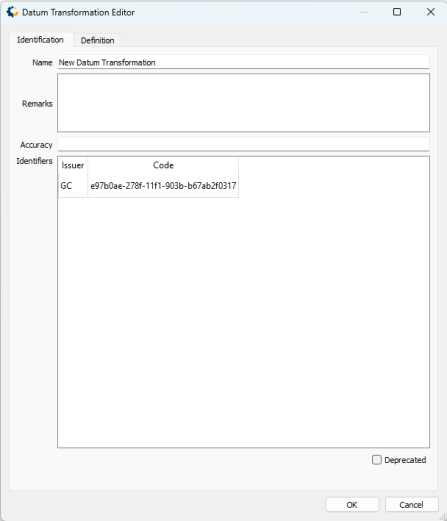
The Identification tab is used to name the object and associate identifying codes with it (if applicable).
- The Name field is where you need to enter the appropriate name for the definition; the name entered is the name that will be used to select the object in the main list.
- The Identifiers list may be used to add identifying codes for an object that may be referenced in other databases. The GC code is a unique identifier which cannot be altered. To enter additional codes, right-click in the space below.
- The Remarks field can be used to add notes on a definition and is optional.
- Deprecated may be checked to indicate an object is no longer being used, either because there are errors in the definition, or because it has been superseded by another object. If this is checked, you will be provided with a date picker to set the date on which the object was deprecated. This will default to the current date.
Definition
The Definition tab is used to define the object's parameters. This will differ based on the type of object that is being created. The relevant details for the most commonly created object types are outlined below.
Creating a Coordinate Reference System Definition
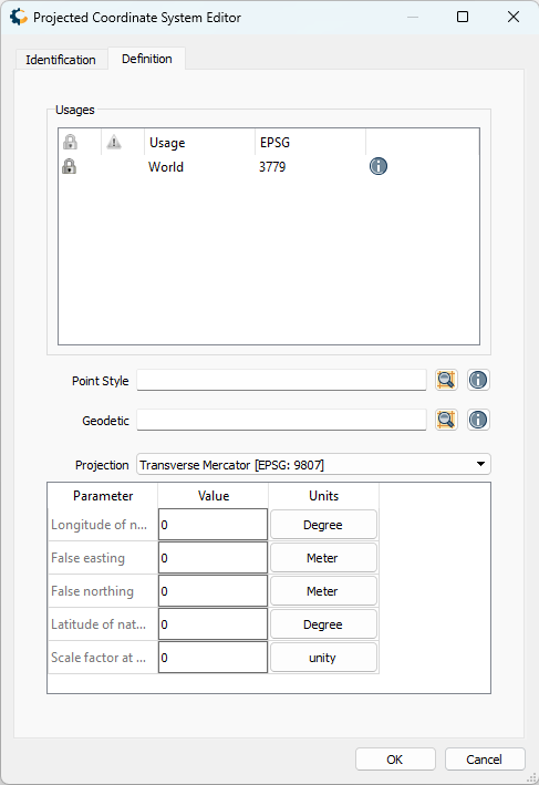
The Definition tab and available parameters will differ somewhat depending on the base type of the Coordinate System (Geocentric, Geodetic, Projected, String, or Vertical).
For all types, a Usage definition must be specified, which contains an Area of Use parameter defining the geographic extent within which a particular object is intended to be used. By default, this is set to World.
Additionally, all Coordinate System definitions require a Point Style, which defines the orientation of axes and the specific units used within the system. For projected coordinate systems, choose the Point Style that uses the correct units for the system.
Projected and Vertical Coordinate Systems require an underlying base Geodetic system that uses the appropriate datum. Use the search button to the right of the Geodetic field to select this datum.
Finally, when creating a Projected Coordinate System, select a projection from the Projection dropdown. For each projection, the parameters needed to define the system will be displayed in the table at the bottom of the dialog. In addition to entering the values associated with each parameter, it is also important to ensure that each unit associated with that parameter is correctly specified.
Creating a Transformation Definition
![]()
Similar to creating a coordinate reference system definition, all transformation definitions require specifying a Usage definition, which contains an Area of Use parameter defining the geographic extent within which a particular object is intended to be used. By default, this is set to World.
The Source and Target parameters define the coordinate systems that the transformation is valid for, and connected to. The Method section allows for the specific type of transformation to be defined. With the desired method selected, the appropriate parameters for the transformation can be entered in the table at the bottom of the dialog. The units associated with each parameter can also be adjusted in this table.
Concatenated Transformations provide a means to chain together multiple Single Transformations, using a version of the Coordinate Transformation selection dialog that is launched by clicking the 'Create' button. The individual Single Transformations are displayed in the table at the bottom of the Definition Panel.
Grid based Transformations require the necessary file be placed within the relevant datasource directory location.
For horizontal grid shift files, the relevant filepath is C:\ProgramData\GlobalMapper\GeoCalc\ShiftFiles.
For vertical grid shift files, the relevant filepath is C:\ProgramData\GlobalMapper\GeoCalc\ShiftFiles\vertical
Once the grid file has been placed in the correct directory, the relevant filename needs to be specified in the table at the bottom of the dialog.
Custom Geoids
Vertical Transformations based on geoid models which are not in the built in datasource can be added using the following steps.
Adding Custom Geoids
- Import the source Geoid grid into Global Mapper.
- From the File dropdown menu, select Export>Elevation Grid Format, selecting Blue Marble Grid in the Select Export format dialog.
- Place the exported BGD file in the following directory: C:\ProgramData\GlobalMapper\GeoCalc\ShiftFiles\vertical
- Navigate to the Select Coordinate System tab of the Configuration menu. Click Edit Datasource.
- Within the Single Transformation folder, select Vertical, and then the relevant geographic region folder.
- Specify the relevant name for the transformation in the Identification tab. In the Definition tab, select the source and target system.
- Enter the filename to the generated bgd file in the Vertical offset file field. In the Path field, enter the relevant sub directory name contained within the ShiftFiles folder. If no new directories were created, this is typically "vertical".