This tool creates a small terrain grid on top of the existing terrain that will modify the terrain in and around the selected areas. This tool can be used to flatten out a site and also to plan for the transition back to the surrounding terrain using slopes or benching and terracing.
Select the area feature(s) with the  Digitizer tool then right-click to Advanced
Feature Creation > Calculate Flattened Site Plan Grid from Selected Area(s). This option is also available in the 3D viewer Digitizer context menu.
Digitizer tool then right-click to Advanced
Feature Creation > Calculate Flattened Site Plan Grid from Selected Area(s). This option is also available in the 3D viewer Digitizer context menu.
When selected the Site Flatten Parameters Setup dialog (pictured below) appears, allowing you to setup the site flattening operation.
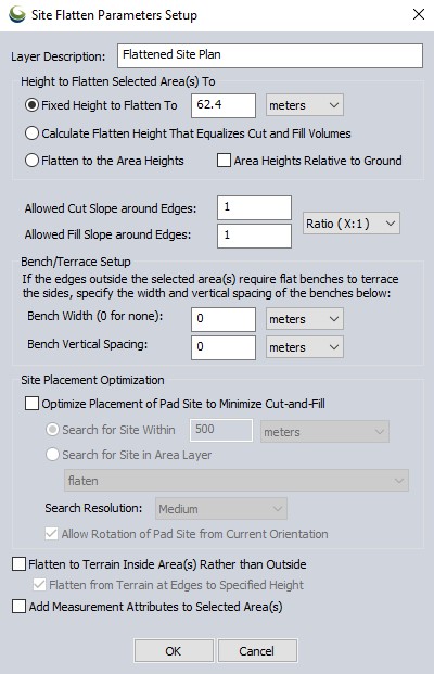
Height to Flatten Selected Area(s) To
Specify the height at which to flatten the areas using the Fixed Height to Flatten To option.
Calculate Flatten Height That Equalizes Cut and Fill Volumes will determine a break-even height at which approximately equal amount of terrain will need to be cut versus filled across the site. This is useful in estimating real-world build site materials so little or no material will not to be brought in or hauled out.
Choose Flatten to Area Heights if the selected areas already contain appropriate elevation values. This option allows flattening to non-level surfaces.
For trenches, ski slopes, ditches and other angled paths, see Move/Reshape Feature >Adjust Elevations to a Single Slope to create a line matching a slope. Then use the  buffer tool to create an area that will also match the slope.
Slope or Bench and Terrace
To slope the edges beyond the site to gradually align with the terrain use the Allowed Cut Slope around Edges and Allowed Fill Slope around Edges values. The slope values can be entered in ratio (x:1), percent or degree format. Select the appropriate slope value format option from the dropdown menu.
To set up benching and terracing, specify values other than 0 for the Bench Width and Bench Vertical Spacing.
Examples
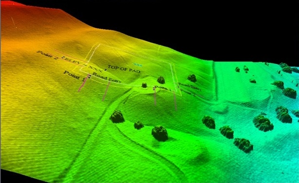
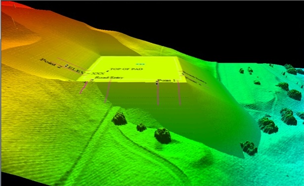
The images below show the 3D viewer before and then after performing a flattening operation on a hillside:
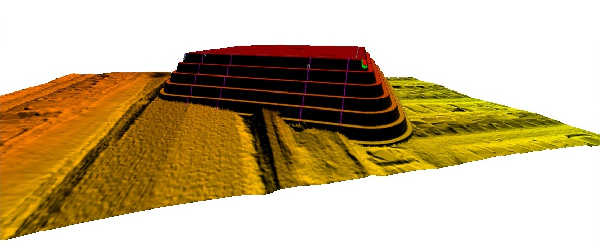
The images below shows the 3D viewer after an operation to flatten a site high above the terrain surface, mainly to illustrate how the terracing works. Note how the new surface matches up with the original terrain surface:
Site Placement Optimization
When Optimize Placement of Pad Site to Minimize Cut and Fill is chosen, this option will search for an optimum place for a flattened site plan based on minimum cut and fill volume within a defined search area when flattening a pad site. Any point or line features also selected with the pad site will be adjusted as well.
Limit the area of search using these options:
-
Search for a site within a specified distance from the pad site.
-
Search for a Site within Area Layer: Choose a loaded layer to search within all area features in that layer.
Search Resolution determines how intense the search will be. Higher resolutions will assess more locations and orientations at the cost of increased processing time.
Allow Rotation of Pad site from Current Orientation will compare different orientations as well as different locations.
Flatten to Terrain Inside Area(s) Rather than Outside
This option creates a flattened site plan grid where all edited terrain is contained within the selected area(s).
Flatten from Terrain at Edges to Specified Height - With this option enabled (default), the generated flattened grid will maintain the original edge heights and begin flattening at the edges of the selected area at the specified slope until it reaches the specified flattening height. With this option turned off, the flattening height will be applied to the edge of the area feature, and sloped inside the area until it meets the original terrain surface.
Add Measurement Attributes to Selected Areas
Adds measurement attributes to both the parent and generated layers. Measured attributes typically include Cut Volume, Cut 2D and 3D Surface Areas, Fill Volume, Fill 2D and 3D Surface Areas, and Break-Even Height.