Adjust Elevations to a Single Slope
This option adjusts the elevations of a line feature to conform to a specified slope measured in degrees. The vertex positions will remain the same, but the 3D segment length or each line and elevation of the vertices will be adjusted so that the line or selected section of the line matches the specified slope.
Select the line feature(s) of interest with the  Digitizer tool, or drag to select a subset of vertices within a line feature. Then right-click to Move/ Reshape Features> Adjust Elevations to a Single Slope.

In the Adjust Elevations to a Single Slope dialog specify the line slope in degrees (+- 60 degrees).
When the entire line is selected, the first vertex of the line will be set at the terrain height (or keep its current value if per-vertex elevations are already set for the line feature). The additional line vertices will have the Z value adjusted to conform to the specified slope.
When a subset of vertices of the line are selected, the selected vertices will be adjusted to match the specified slope. The first selected vertex in the line (per the order listed in Feature Vertex List) will keep its height. The subsequent vertex will adjust conform to the specified slope.
When a set of non-consecutive vertices are selected in a line, all segments between those vertices will be adjusted to conform to the specified slope.
Adjusting the slope a line will impact the 3D length of each line segment. The X and Y position of each vertex will not be changed, only the Z value is modified.
Examples
When used in combination with the Calculate Flattened Site Plan tool, you can use the Adjust Elevations to a Single Slope tool to create a small terrain grid on top of the existing terrain with a specified slope.
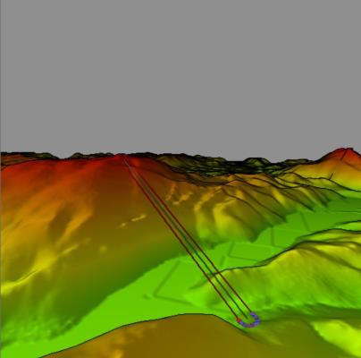
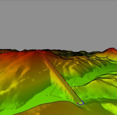
The example below shows a 2 vertex line feature that was given a slope of -10 degrees. The buffer created from the line inherited the adjusted slope value. Then, the Calculate Flattened Site Plan tool with the "Flatten to the Area Heights" option was used to create a raised and sloped terrain feature:
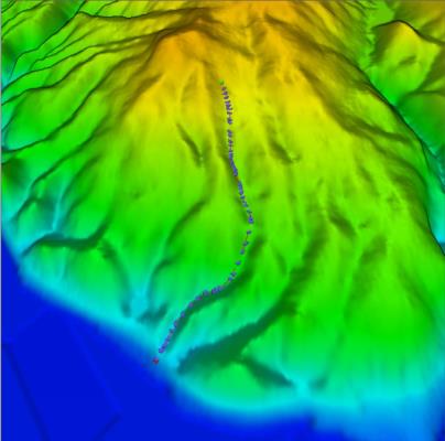
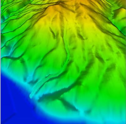
The next set of images show a similar example of before and after the Calculate Flatten Site Plan tool was used on a polyline with an adjusted slope of 8 degrees, and a buffer. Note how the slope is maintained between each vertex: