
The Path Profile tool displays a vertical profile along the specified path using loaded elevation datasets. In addition, this tool proves the ability to create line of sight calculations along the defined path. Perpendicular profiles allow for stepping through a line in cross-sections, similarly with parallel profiles. With Global Mapper Pro enabled, the Path Profile tool displays Lidar data and enables the Lidar Toolbar for manual classification and editing. Global Mapper Pro also enables 3D Feature Extraction from the Path Profile window.
The
path profile tool is located on the Analysis Toolbar and in the Tools menu. Profiles can also be generated by selecting existing line features using the digitizer, then navigating toAnalysis/ Measurement in the Digitizer menu or context menu to Generate Path Profile Along Lines.
Quick Tips for Creating a Path Profile
To define the path along which to generate the 3D path profile:
1. Select the path profile tool button from the Analysis Toolbar or from the Tools menu.
-
Alternatively, path profiles can be created from an existing line feature by selecting the line feature with the Digitizer Tool, and choosing the Generate Path Profile Along Line(s) icon in the Digitizer Toolset, in the Information section.
2. Press and release the left mouse button at the position where you wish to start the path.
- Left click to add vertices along the path, if desired.
3. Right click on the last location to finish drawing the path.
4. The Path Profile/Line of Sight dialog will appear (pictured below), displaying the 3D path profile of the selected path.
Enable a Parallel or Perpendicular Profile from the Path Profile Settings menu. This allows for stepping through sequential cross sections of the path, rather than profiling along the length of the path.
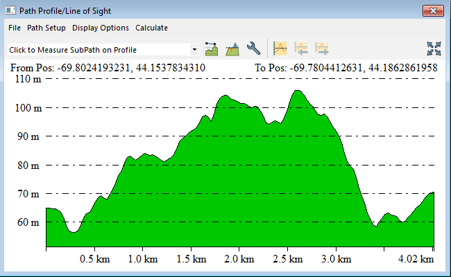
The Path Profile/Line of Sight dialog displays the 3D path profile and provides several options related to the profile. A vertical scale is displayed on the left side of the profile window. The start and end coordinates of the path are displayed at the top of the profile window.
 Generate Path Profile from Line
To create a Path Profile from an existing line feature, select the line feature in the workspace using the Digitizer tool, and either:
-
In the Digitizer Toolset, choose the
 icon in the Information section, or
 -
Right click in the workspace and selecting the Generate Path Profile Along Line(s) option from the Analysis/ Measurement submenu.
Path Profile with Terrain Data
If more than two points are in the path, the intermediate points will be marked in the profile window with a yellow dot. These intermediate points can be turned off using an option available in Path Profile Settings. The path profile window is re-sizable and can also be docked in the main application window.
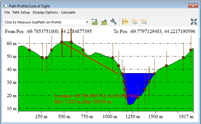
With water display enabled on the Vertical Optionstab, the water line will be displayed along the path.
Moving the cursor over the profile window displays information about the current cursor location along the profile, including its position and profile elevation. The cursor location in the profile window will display in the 2D Map view as a red X, and in the 3D view as a red dot connected to the profile line.
Get information about a portion of the profile (a sub-path) by left clicking to start a sub-path definition, then left-clicking again at the end of your desired sub-path. Details about the sub-path, like length, elevation change, and slope, will then be displayed on the bottom of the profile window.
Right-clicking on the profile window brings up an options menu that allows the user to change the start and end positions, select the units (meters or feet) to display the elevations in, configure display of the path profile, and display a dialog containing details about the path. These options are also available under the Display Options menu on the dialog.
See Also Using
the Path Profile Tool with Lidar/Point Cloud Data [Requires the Global Mapper Pro]
Multiple Terrain Layers
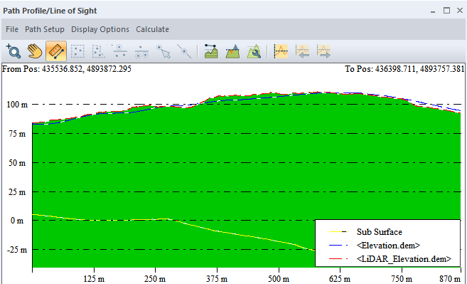
If Multiple Elevation layers are loaded, each layer may be shown with a dashed line of a different color. A legend can also be displayed on the profile to identify the line features. The color used for each layer is picked from a pre-determined list of colors. For more information see Path Profile Settings . To customize the colors, right-click on the profile itself and select the option on the right-click context menu to Specify Color for Terrain Layer Line... and set the color to use for any of the terrain layers.
Editing 3D Height of a Line Feature in the Path Profile View
-
A path profile view can be initiated from a 3D line feature by selecting the line feature with the Digitizer Tool, right clicking, and selecting the Generate Path Profile Along Line(s) option from the Analysis/Measurement submenu.
-
In the Path Profile/Line of Sight dialog, select Extract Lines/Areas from Perpendicular Profiles. Select Yes to edit the selected line feature. Selecting N will create a new line feature.
-
If not already turned on, follow the prompt to turn on the Perpendicular Profile View.
-
Enter a Distance Criteria which will specify the total length for each segment that is drawn perpendicular to the selected feature.
-
Similar to the Custom Feature Extraction tool, the vertices of the line can be edited by adjusting the relative location of the red dot within the Perpendicular Profile view.
-
In the Perpendicular Profile Feature Editing dialog, users can toggle between the location of the existing vertices within the feature, as well as using the Move to Next Perpendicular or Parallel Profile buttons


-
Select the Save Feature button to apply the changes made to the vertex heights to the underlying 3d line feature.