Ground Control Points can be added in the Pixel-to-Points tool optionally to adjust the horizontal and vertical positioning of the point cloud and other generated products. With no ground control points, the products will be positioned using the input image metadata.
In general, Ground Control Points are used in conjunction with recognizable features in the input images. The pixels that comprise the features are aligned to a known location via the GCP (X, Y and Z coordinates). Typically the identifiable points or targets are surveyed using equipment of higher accuracy than the device used to capture the imagery. However, in dire cases, ground control point locations could also be generated through manually creating point features referenced to additionally loaded orthorectified imagery, such as available from high resolution Online data sources.
When targets, or other unique features, in the images are used as GCPs, the Auto-Place option can be identify where in each image the GCP is located based on user-defined examples of the target.
To save ground control point image positions for future processing or editing use the Save a P2P Workspace File option from the main Pixels to Pionts window.
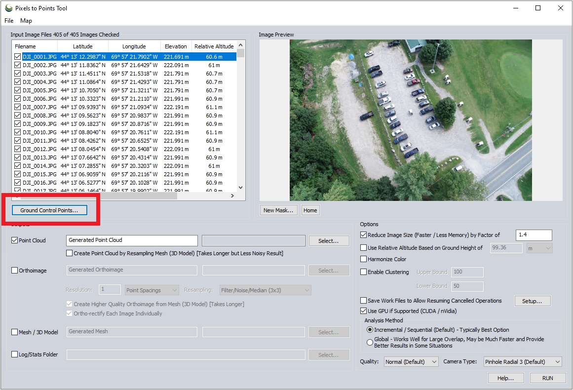
Click Ground Control Points... in the  Pixels to Points dialog to open the Ground Control Points manager.
Steps for loading and placing ground control points within images
1. After loading the image files into the Pixels to Point tool, click the Ground Control Points button to open the Ground Control Points manager.
2. Load the ground control points into the top left window using the buttons located below the window.
3. Click on a point to populate the Suggested Images list with the images that are assumed to contain the GCP based on point location and estimated image bounds.
-
Click on an image to see it previewed in the Control Point Placement window.
4. If the feature in the image used to mark the GCP is a unique shape, such as the red target shown in the example screenshot, use the Define Target in Image button to create a bounding box to train Global Mapper on what the target looks like.
Otherwise, use the Add Control Point to Image… button to manually place control points by clicking in the image preview. See Control Point Placement window below for more details.
5. Choose an image where the GCP target is clearly displayed.
6. Click Define Target In Image. Then, to define the target, click on the center of the target (where you want the control point to be placed) and drag your mouse outwards until the box covers the target.
7. A prompt will appear with the option to automatically search for the target in possibly overlapping images. Click yes.
8. Once processing has finished, you will need to confirm the locations:
Confirming GCP Locations
Only confirmed point locations will be included during processing; unconfirmed points will be ignored.
Images will be color coded based on GCP placement confidence. To improve accuracy to the best extent, confirm as many GCP locations as possible.
- Images with Confirmed control point locations that you have approved will be highlighted blue.
- Auto-placed markers that have not been verified are green.
- Images that have Possible Overlap with the GCP location, but don’t contain a target that could be visually identified, are yellow.
To confirm a GCP location, click on an image from the list and locate the target in the image.
If necessary, adjust the control point location by clicking and dragging the point feature. Adjusting the location will automatically confirm the image. (Note: point symbol colors and labels can be changed by double-clicking on the ground control point from the list.)
If the point is correctly placed in the image, confirm it’s location by checking the box next to the image name.
Control Point Placement window
The Control Point Placement window displays the image highlighted in the input image file list.
To zoom the preview image, locate the cursor over the part of the image that is of interest, and roll the mouse wheel. The image can also be zoomed by left-click and right-click of the mouse. A left-click will zoom in at the cursor location. A right-click will zoom out.
Click and drag the mouse wheel to pan the image.
If a control point has been added to the image, it is selectable by left-clicking. The cursor will change to an arrow when over the added point, allowing it to be selected. A red box will appear around the point indicating its selected state. Left-click and drag to move the selected control point.
Load from Point Layer
Use this option to import ground control points from a loaded layer in the workspace.
Load from Text File
Use this option to open a .txt or .csv file that contains point features, from your computer.
New Point...
Enter the known coordinates of the ground control point. Double-click the named point in the Ground Control Points list to bring this dialog back up for an already added Ground Control point.
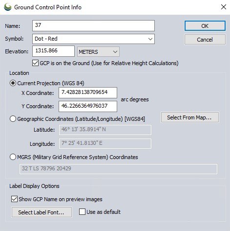
Name- Specify a name to identify the ground control point.
Symbol - This is the point symbol that will be displayed on the image previews that contain this ground control point.
Elevation - The elevation value is important to vertically align the output point cloud. The default value will come from the image metadata but should be customized for improved vertical accuracy.
-
GCP is on the Ground (Use for Relative Height Calculations) - This option is relevant for creating a ground surface for height above ground estimates. Enabled by default, this option assumes that all GCPs were collected on the ground surface, and not on a pole or otherwise offset.
Location - Specify the coordinate location of the ground control point. The current projection is set from the Configuration display projection, and if no data is loaded into the map it will default to Geographic WGS84. The Select From Map... button will also be available in the location section, only when there is data loaded in the main map view.
Label Display Options - Specify the display of the GCP labels in the Image Preview viewer.
Remove Selected
Press the remove selected button to remove the entire Ground Control Point from the list of Ground Control points.
To remove the point from only one input image, press the point to select it. Then press the Delete key to remove the Ground Control Point instance.
Add Control Point to Image...
This button is located under the Image Preview. Press this button to add a control point to the current image preview. It may be necessary to first click on the image to zoom, or use the mouse wheel to zoom in on the image preview.
Once a point is added to the image, it can be updated. Click the point on the image to select it. Drag to move or press the Delete key on the keyboard to remove the point on the image.
Context Menu
Right-click on the Ground Control Points list to see the following options:
-
Edit Ground Control Points... (Double Click) - Use this option to modify the X,Y,Z of the Control Points, the Name, symbol style, and label information used.
-
Load Control Points as Point Features in Main Map - This option will create a new Ground Control Point layer in the 2D map view, with labels and styles matching the points in the Pixels to Points dialog.
-
Save Control Points to Text File - This will save a text file of the Ground Control Point locations, as while as any images that have been marked as containing them, with the corresponding pixel X and pixel Y coordinates of the image. This can be loaded into a new Pixels to Points workspace to reuse just the control points.
Ground Control Report
Once the tool has been run with specified Ground Control Points, the Input Image list will populate with columns of additional statistics based on the fit of the input control points. This final complete operation dialog will also display the overall camera position fit error.