 Guided Breakline Extraction
The Guided Breakline tool creates individual 3D breaklines based on user-placed seed points on digital terrain model (TIN or DEM) layers. Compared to the similar tool, Generate Breaklines, that searches for specified values within an area, the Guided Breakline tool allows the user to point to individual terrain features in the data to be extracted. This tool provides control for precisely extracting specific linear features such as curbs, road edges, shorelines, ditches, etc.
A Breakline![]() A Breakline is a 3D line feature that marks a sharp, sudden change in the terrain's slope or elevation, defining features like ridges, valleys, road edges, or the tops and bottoms of banks. is a 3D line feature that marks a sharp, sudden change in the terrain's slope or elevation, defining features like ridges, valleys, road edges, or the tops and bottoms of banks.
A Breakline is a 3D line feature that marks a sharp, sudden change in the terrain's slope or elevation, defining features like ridges, valleys, road edges, or the tops and bottoms of banks. is a 3D line feature that marks a sharp, sudden change in the terrain's slope or elevation, defining features like ridges, valleys, road edges, or the tops and bottoms of banks.
Choose from three types of guided breakline extraction: Ridge, Valley, or Edge. Place the initial seed point (line vertex) at the start of the desired feature. As you place each subsequent seed point, Global Mapper analyzes the curvature of the terrain between points and connects them to create a breakline. Continue placing seed points until you have reached the end of the feature.
This tool creates individual breaklines. To create multiple breaklines simultaneously over an area or layer see Generate Breaklines from Terrain Grid.
The Guided Breakline Extraction tool can be found in the  Analysis toolbar, and the Terrain Analysis menu.
|
|
This tool requires Global Mapper Pro |
Quick Steps to Generate a Guided Breakline:
- Select the Generate Breaklines tool.
- Verify that the desired Feature Layer (for saving breaklines) and Terrain Layer (for analysis) are selected in the dialog.
- Choose which Breakline Type best describes the feature begin extracted: Ridge, Valley, or Edge
- Click the Place Seed Points button, if not already enabled when the tool opened. The cursor indicate the"Guided" mode.
- A seed point is a user-placed point (vertex) that guides the automatic breakline path-finding algorithm.
- In the workspace, click to place the first seed point at the beginning of the feature to be digitized.
- Cell Snapping - When placing the first point using the Ridges or Valleys method, notice Snapping is enabled. The breakline tool will automatically guide the mouse to the local point of maximum elevation within the Snap Tolerance around the cursor for Ridges and the minimum elevation for Valleys. This helps ensure that the initial point feature is placed correctly. The initial seed point placement is critical for best results.
- Snap tolerance can be set in Advanced Vector Display Configuration.
- Cell Snapping - When placing the first point using the Ridges or Valleys method, notice Snapping is enabled. The breakline tool will automatically guide the mouse to the local point of maximum elevation within the Snap Tolerance around the cursor for Ridges and the minimum elevation for Valleys. This helps ensure that the initial point feature is placed correctly. The initial seed point placement is critical for best results.
- Click to place additional seed points along the feature to guide the breakline. Detailed features may require more vertices to be placed.
- End the breakline by either clicking escape, right-clicking, or clicking the Finish Seed Points button.
- The new breakline will be added to the layer specified in the Feature Layer setting.
Guided Breakline Extraction settings:
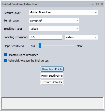
Feature Layer
Choose or create a layer to which the extracted breakline features will be saved. The default is a new layer "Guided Breaklines".
Terrain Layer
Specify the terrain layer for breakline analysis.
Breakline Type
Select the Breakline Type that best describes the feature you are extracting.
Breakline extraction in Global Mapper is based on a curvature analysis. Global Mapper analyses the terrain by creating an underlying curvature grid layer that identifies discontinuity in slope. Each Breakline Type uses a unique curvature analysis method designed to follow particular types of features, allowing Global Mapper to interpolate between placed seed points to complete the breakline.
Ridges - Follow the crest or peak of terrain where water would flow away in both directions.
Valleys - Follow the lowest points of a drainage channel where water would collect.
Edges - Follow a distinct break or transition in the terrain's grade, such as a curb or toe of slope.
Sampling Resolution
The default value for Sampling Resolution will match the resolution of the chosen Terrain Layer. When a new terrain layer is chosen, this value will automatically update to match the new layer.
This value determines the resolution of the curvature layer that the breakline is generated from. The curvature layer is not visualized, and is calculated continuously as seed points are placed. Increase this value to ignore noise or small changes in curvature.
Slope Sensitivity
The default setting is best for ensuring that the breakline stays consistent when crossing other features. Increasing this will cause the line to avoid slope changes that are in opposition to the type the line is running along.
Smooth Guided Breaklines
With this option enabled, the placement of some of the interpolated vertices (between seed points) may be adjusted to create a smoother line, reducing the angle between segments.
Right-click to place the final vertex
If unchecked, right-clicking will end the line without adding an additional vertex. Check this box to both end the line and place the final vertex at the right-clicked position (matching similar digitizing functionality in Global Mapper).
Place Seed Points
Click to enable the cursor mode for placing seed points in the workspace. A seed point is a user-placed point (vertex) that guides the automatic breakline path-finding algorithm.
Finish Seed points
Click to disable the seed creating cursor mode. If a feature is being guided, this ends the feature at the last placed seed point.
Restore Defaults
Restores the default settings for Guided Breakline Extraction.