Parallel and Perpendicular Path Profiles are features of the Path Profile tool that provide the ability to look at subsections of the path profile. These additional profiles function similarly to one another, but they are differentiated by their perspectives being either parallel or perpendicular to the original path profile. Only one type of perspective profile can be enabled at a time.
Parallel and Perpendicular paths can be enabled by clicking the Path Profile  Settings button from the Path Profile window, and choosing the Perpendicular/Parallel path profiles tab.
Perpendicular Path Profiles
Perpendicular Path profiles, or cross profiles, display a sequential series of profiles across a path, rather than along it.
To enable Perpendicular Path Profiles:
With the  Path Profile tool enabled, select the
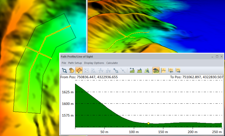
  Show Perpendicular Profiles button, or click the settings button on the Path Profile window. Check Display Series of Profiles Perpendicular to Path to create cross sectional views along the path.
Use the 
 left and right arrows on the Path Profile window toolbar (or use the left and right arrow keyboard keys when the path profile window is selected) to step through the perpendicular profiles (cross sections) along the path.
The spacing of the sections along the path and the width / length of the cross section can be set in the settings for the path.
-
The cross sections (perpendicular profiles) can be spaced to line up with each vertex and endpoint of the line, be calculated at fixed distances along the line, or they can equally subdivide the path to create a given number of profiles.
Use the navigation tools or mouse wheel and shortcuts to zoom into a section of the cross profile. For more information see Navigating and Zooming in Path Profile
Perpendicular Profile Settings
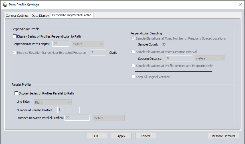
Choose the Display Series of Profiles Perpendicular to Path option to enable the perpendicular view. This allows stepping through cross sections along the defined path.
-
Perpendicular Path Length - allows you to specify the total width of the cross section.
Restrict Elevation Range Near Extracted Features - This option allows for restricting the path profile elevation range relative to features being extracted by Custom Feature Extraction. The elevation will be restricted to within some elevation distance of the min/max range of the feature elevations. For example, if you have a range of 2m and your features cover from 5-8m, the profile will show at most 3-10m. This makes it easy to digitize things with a very tight vertical range (like curbs) when you might have data showing a lot more, like trees and buildings along with the road features.
Perpendicular Sampling
Sample Elevations at Fixed Number of Regularly Spaced Locations - This setting will generate Perpendicular Profiles at evenly spaced location along the length of the line.
Sample Elevation at Fixed Distance Interval - This will generate Perpendicular Profiles at a fixed distance along the length of the line.
Sample Elevations at Profile Vertices/ Endpoints Only - This option will generate Perpendicular profile / cross section at each vertex of the line.
Keep All Original Vertices - This option is available when using Sample Elevations at Fixed Number of Regularly Spaced Locations or Sample Elevations at Fixed Distance Interval. In addition to generating the specified perpendicular profiles, it will include profiles at each vertex and the endpoints of the line feature.
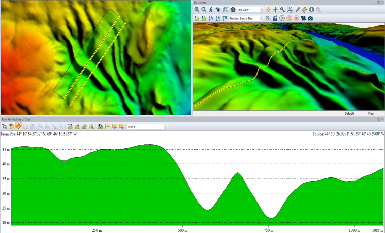
Parallel Path Profiles
Parallel Path Profiles display a sequential series of profiles parallel to the original path. It is possible to create parallel line features on left, right, or both sides of selected or drawn original profile line.
To enable Parallel Path Profiles:
With the Path Profile tool enabled, click the settings button on the Path Profile window and chose the Perpendicular / Parallel Paths tab. Check Display Series of Profiles Parallel to Path to create the parallel views.
Use the left and right arrows on the Path Profile window toolbar (or use the left and right arrow keyboard keys when the path profile window is selected) to step through the parallel profiles along the path.
The spacing of the sections along the path and the width / length of the cross section can be set in the settings for the path.
-
The parallel lines can be drawn at an specified distance from the original line.
Use the navigation tools or mouse wheel/shortcuts to zoom into a section of the cross profile. For more information see Navigating and Zooming in Path Profile
Parallel Profile Settings:
Display Series of Profiles Parallel to Path - check this box to enable Parallel Profiles.
Line Side - Choose which or both side of the original path profile line to visualize. Right and left are determined from the perspective of the line start.
Number of Parallel Profiles - Set how many profile lines should be generated.
Distance Between Parallel Profiles - set the space between each parallel profile in the Path Profile Settings . The distance number of profiles combined determines how far away from the original profile the parallel profiles will extend.