Environment

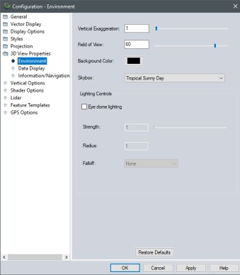
The 3D View Environment Configuration contains settings to set up the skybox for viewing data in 3D. Environment options that can be altered here are data height exaggeration and water display, lighting controls, and field of view.

Access the 3D View Environment Configuration by selecting the configure button Configuration button from the 3D Window. Or, select the Configuration button from the File Toolbar or Tools menu, and navigate to the 3D View Properties section. In the Configuration dialog navigate to Environment section in the 3D View Properties folder.

Vertical Exaggeration

Use the slider or enter a value to control the vertical exaggeration. This is also available as buttons on the 3D Toolbar. For more information see Vertical Exaggeration.

Field of View

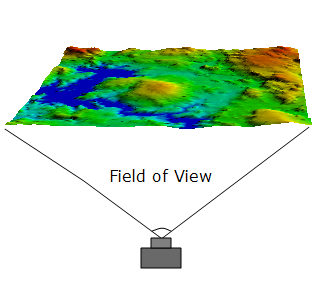
The Field of View is a degree measurement that defines how wide of a view the camera has in 3D. The default field of view is 60 degrees.

Press F11 to increase field of view by 5 degrees. Press CTRL + F11 to increase field of view by 1 degree.
Press F12 to decrease field of view by 5 degrees. Press CTRL + F12 to decrease field of view by 1 degree. …

Background Color

Specify the background color to use in the 3D view. This color will only be visible when the Skybox Drop-down on the 3D toolbar is set to None (Solid Background).

Skybox

The drop down menu may be used to set a specific sky texture background or to set a solid background (None).
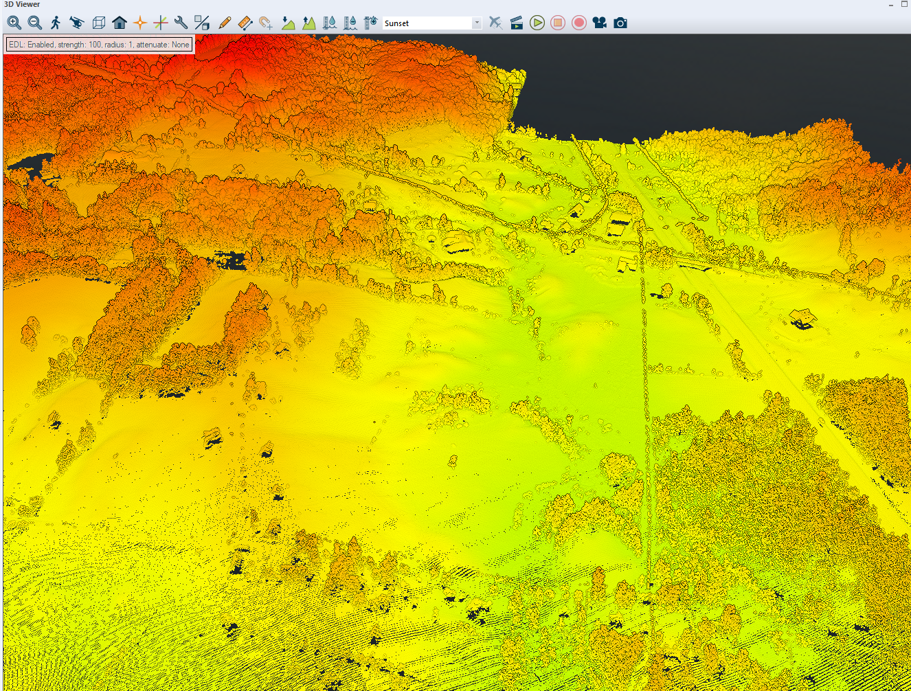
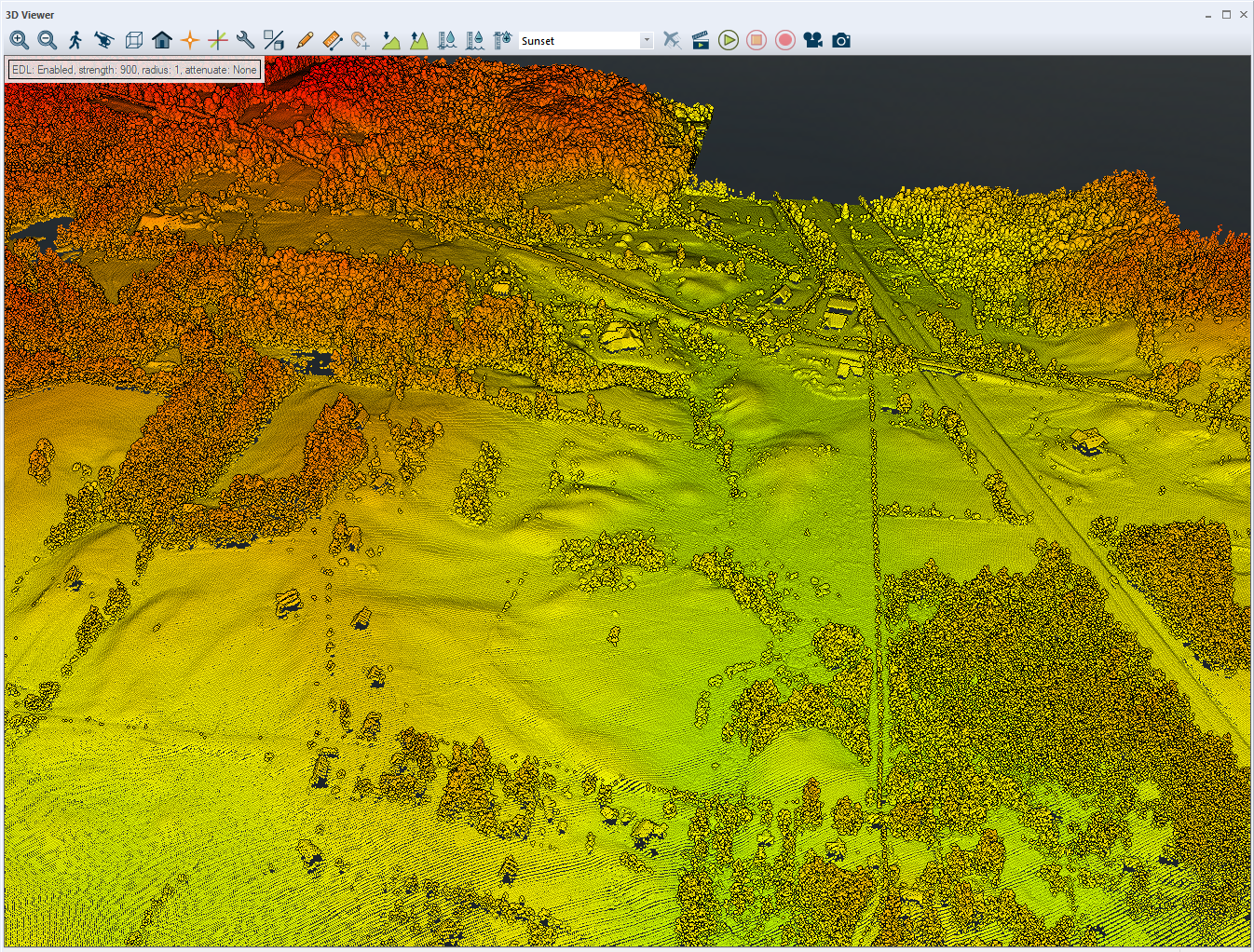
To create a custom skybox:
1. Create a folder in C:\Program Files\GlobalMapperXX_64bit\SkyboxTextures
2. Add 6 image files labeled Back, Front, Up, Down, Right, Left. They should be .bmp, .jpg, or .png formats. See other existing skybox textures for examples.

Lighting Controls

Eye Dome Lighting (EDL)

Enabling this option can give users a better visualization of 3D data by enhanced lighting techniques to highlight depth and edges in the middle ground of the scene. It will improve the ability to tell what objects in the 3D scene are in front of other things, but adding a dark edge around the data. Lidar will appear to have outlines which may give you a better visual of structures and features in the lidar, and also a better sense of depth while viewing data. EDL may be most useful on non-RBG or non-colorized Lidar. EDL lighting also impacts 3D models, 3D vector data and terrain data. At very low horizon angles, eye dome lighting can add additional darkening to the scene.

Example:

This example shows the Strength setting set at 100. EDL effects are not as strong or noticeable, but you can start to see outlines of trees and buildings.

This example shows the Strength setting at 900. EDL is much more distinct at this level as you can visualize the shadow effect on terrain, and see clearer outlines of tree, and buildings.

Strength

This slider adjusts the intensity of the EDL settings. Acceptable values can be between 0 through 1000. Higher values will show a much stronger effect of depth perception and outlining of features in Lidar.

Radius

Enter a pixel Radius value. EDL works by analyzing the depth of image around each pixel. Higher values strengths the effects of EDL. Acceptable values between 1 and 4.

Falloff

Falloff settings can gently change the display. EDL works by analyzing the depth of image around each pixel from each point. The effect looks at the differences in depth, from the center pixel of that circle and only considers points on that circle that are farther away (closer ones are ignored). Pixels which have "close" neighbors don't appear to change much visually. But those whose neighbors are much farther away change a lot (perhaps an isolated tree in a field, or a tall building stand out more). The idea of "close" changes based on how the falloff gets used, so it brings out edges (since they have distant neighbors).

  • None -No falloff option is applied. This is the default setting. EDL gives an equal weight to each depth difference. A scale factor of 1 is applied to each depth difference.
  • Linear - Keeps the scale factor 1 in the center, but allows it to fall off to 0 linearly on the edge pixels. (when viewing lidar at an angle to view a horizon, data appears brighter than using None)
  • Inverse Linear -scale is 1 on the edge and falls to 0 in the interior. (when at same angle, lighting appears like the none setting)
  • Geometric - keeps it 1 in the center, but allows it to fall off much faster to 0, non linearly, on the edge pixels (when compared to Linear at the same angle, lidar appears just slightly darker)
  • Inverse Geometric -scale is 0 from inside, to 1 on edge but allows it to fall off much faster to 1, non linearly, on the edge pixels

Water Display

Display Water in the 3D View

Toggle on and off the display of water. This is also available as a button on the 3D Toolbar.

Water Level

Use the slider to adjust the water level height and the units of measure. Increment buttons are also available to control this on the 3D Toolbar.

Water Level Increment

Specify the increment used when increasing or decreasing water level with the toolbar Increase water Level and Decrease Water Level buttons .