Global Mapper supports loading and exporting a number of 3D Model formats.
Unlike standard vector data, 3D models contain a 3D mesh structure where various 3D points are connected via edges and faces. While 3D vector features can only contain elevations at the edge of an area, the 3D mesh format contains internal vertices that allow for representing more complicated 3D geometry. Compared to a more simple Triangulated Irregular Network (TIN), 3D meshes may also have face and vertex normals that indicate the front or backside of the face, and control other shading and lighting effects. Some 3D models also contain texture(s), which are pictures that are mapped to the vertices, and create a more photo-realistic surface, similar to image draping.
Supported 3D Model formats:
The following formats will render 3D models when loaded into Global Mapper
- 2DM File: *.2DM
-
3DS (3DS Max): *.3ds
-
Blender : *.blend
- Collada: *.dae
- FBX (Autodesk Filmbox): *.fbx
- OBJ (3D Printer Friendly): *.obj
- Openflight: *.flt
- PLY (Stanford Polygon Library) : *.ply
- SKP Sketchup : *.skp
- STL (StereoLithography) : *.stl
- OBJ (Wavefront): *.obj
- Google Earth KMZ (may contain SKP or DAE model)
- IFC (Industry Foundation Class): *.ifc
The additional formats listed below may have TIN components or are treated as 3D objects or meshes in other software.
- 3D PDF
- Anuga Triangulated Mesh Format
- AutoCAD DXF 3D Face/TIN, Mesh, or Point Files
- AVS UCD Format
- BT (Binary Terrain) Elevation Grid Files
- CityGML
- Delft3D (LDB) Files
- ESRI TIN Read more...

- LandXML
- MicroStation DGN Format
- Orca XML
- Terragen Terrain Format
- U3D (Universal 3D)
- Unity RAW Terrain/ Texture
- VRML, VRML World File
- Vulcan3D Triangulation (.00t) Files
Loading 3D Model formats
To integrate 3D Model formats with other spatial data, the projection and model orientation and units must be specified.
Projection
Most 3D model formats can be placed with a custom Orthographic Projection, where distance is measured away from the origin of the X,Y and Z axes.
Some 3D model formats support geo-location of the model, which specifies the Latitude and Longitude location of the origin. If this is not available for the model type, or it is not recognized from the file, manually specify the Central Latitude and Central Longitude in the projection dialog for the orthographic projection to correctly locate the origin of the model in Geographic Coordinates. The Planar Units and Elevation Units can also be set to match the model units.
The 3D model can also be placed in a location using the Pad Site placement tool.
3D File Import Options
The 3D File Import options dialog will also appear when loading most 3D model formats.
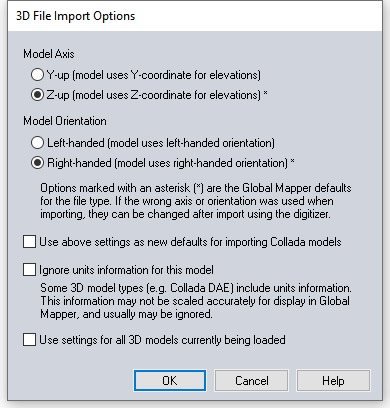
Model Axis - Different 3D model formats label the axes differently. The default for the file format type will be noted with an asterisk. Some formats have a standard orientation and others are more flexible. If the model axis is specified wrong, the model will load on its side. See Mesh Orientation to change this once the model is already loaded.
Model Orientation- Specify whether the model is left-handed or right-handed. The default for the file type will be noted with an asterisk. This defines whether the axis coming forward is positive (right-handed) or negative (left- handed). If the orientation is specified incorrectly the model will appear rotated and inverted. See Mesh Orientation to change this once the model is already loaded.
Use above settings as new defaults for importing model type - Check this option to change the default settings for the file format extension. This modified the default selection this dialog and changes the asterisks when 3D models of this extension are loaded.
Ignore units information for this model - some 3D model formats include unit information that does not scale properly. If the 3D model is not scaled correctly, use this option to ignore the unit information in the model.
Use Setting for All 3D Models Currently Being Loaded - check this option to skip the dialog and use the same load settings for subsequent 3D models.
3D Texture and Color
Some 3D model formats support applying image files to the faces of the model for a more realistic looking model. Global Mapper will load these texture files if they are included in the model, and they will display in the 3D viewer. The 2D Planar map view will show the texture (starting in Global Mapper 20), and at a large scale will also display the mesh structure.
If Global Mapper is unable to locate the folder that contains the texture files, a prompt will appear to specify the location of the texture folder, or skip loading the texture.
Set the display of textures in 3D in the 3D View Configuration.
3D Transparency
The 3D viewer supports transparency, but there are a few limitations.
Transparency only goes 2 layers deep. You won't be able to see the 3rd layer even if the first 2 are both transparent.
3D model textures don't render with variable transparency. Models will automatically be forced into binary transparency.
PNG files with transparent or opaque pixels are functionally limited in the 3D viewer.
Keyboard shortcut: 3D texture display can be toggled on and off in the 3D view using the hotkey T.
To view the 3D texture, select the mesh with the digitizer tool and choose Edit. Alternately, select the mesh with the digitizer tool and right-click to View the Texture for the Currently Selected Mesh. For more information see Mesh Feature Style
Editing 3D Models
- Partition Mesh
- Simplify Mesh
- Crop Mesh
- Move Selected Feature
- Delete Selected Vertices
- Convert a 3D Model / Mesh
3D Point Symbols
3D models can also be applied to point features as a 3D point symbol. 3D point symbols are ideal for use with models that represent more generic types of objects, rather than a specific model that represents something that only appears in one location, such as an exact building replica.
Global Mapper has built in 3D models, or custom 3D symbols can be created using any of the supported 3D model formats. For better performance in the 3D viewer, it is recommended to use more simple models for custom point symbols that will need to render many times in the 3D viewer. For more recommendations for custom 3D point symbol models see Recommendations:
To render a 3D point symbol, the point feature must have a recognized elevation value and height value. [If there is not height value specified, or the height is 0, the model will be scaled based on the 2D symbol size].
The feature must have a 3D symbol specified for the point style, either for the point individually, for the layer the point is in, or based on the feature type.
The Altitude Mode and Model Placement settings determine how the 3D model is placed in the location.
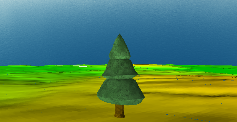
Create 3D points example:
There are multiple ways to implement 3D point symbols depending on what the elevation and height attribute values represent, and how the model is oriented. This is one example of how to create 3D point symbols.
Create 3D Trees
- Create a new point features using the
 . Create Point/ Text feature tool in the Digitizer (Create) Toolbar representing the locations of the tree.
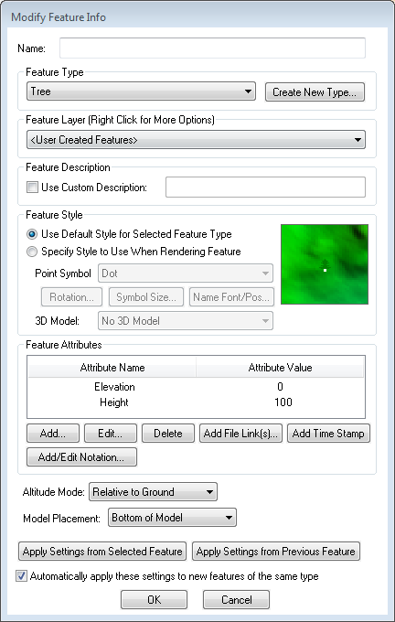
 - On the Modify Feature Info dialog set the Feature Type to Tree.
- Use the Add... button to add an attribute named elevation with a value of 0.
- Use the Add... button to add a second attribute named height, with a value representing the height of the tree above the ground.
- Set the Altitude Mode to Relative to Ground
- Set the Model Placement to Bottom of Model
-
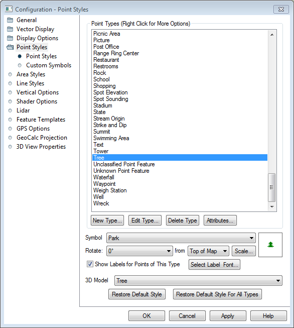
In the Configuration
 Dialog go to Point Styles and locate the Tree Point Type. Select this type and assign in a 3D Model. There are built in models for Tree and Pine Tree to choose from, or use the Custom Symbols page in the Point Styles folder to load another model.
 -
Open the
 3D Viewer to see the 3D point symbols.