If the Show Area and Line Vertices option is enabled (Shift+V is a keyboard shortcut to toggle this setting), you can also select individual vertices on area and line features. You must select vertices before accessing the Digitizer right-click menu options. With vertices selected, the Digitizer submenu Vertex Editing will appear, with options that allow you to work with individual vertices in area and line features appear in the right-click options menu. Selected vertices will be shown on the display with a circle around them.
To select vertices, simple left click near a vertex to select the closest one if any are nearby, or drag a box to select all vertices within the box. Holding down the CTRL key will add to the current selection. If you hold down the S key when left clicking, only vertices from already selected lines or areas will be considered.
For further information on the list display of mesh feature vertices, see Mesh Feature Style.
Keyboard Shortcuts
- SHIFT+V - Show area and line vertices
- S - Only select vertices from already selected features
- CTRL - Add to current selection
The options in the Digitizer right-click menu under Vertex Editing include:
Edit Feature Vertices
Selecting this option brings up the Feature Vertex List dialog (below). In this dialog vertex position, elevation, and segment length may be edited. Any vector features with a "ePolyLineM" or "ePolyLineZ" information will display in separate Measure columns.
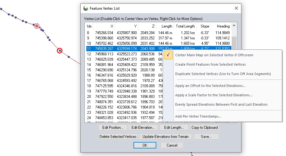
Select a vertex from the list to see the segment and vertex highlighted on the map display. The selected vertex may be edited with the buttons.
Edit Position
Modify the X and Y coordinates of the currently selected vertex.
Add Elevations…
Add or modify the elevation value of the currently selected vertex. If there is no Z or Elevation column in the vertex list, per vertex elevations have not been enabled. There will first be a prompt to enable per vertex elevations and create this column. It will automatically populate all vertices with any existing feature elevation attribute.
Adding or editing elevation values for a line will alter the slope values calculated and displayed for each vertex. The slope is the slope of the line segment from the selected vertex to the next listed vertex.
The elevation unit will be displayed in the column heading. The unit interpretation of the elevation numbers can modified in the Elevations Tab (Vector Data)
Edit Length
Specify the length of the subsequent line segment. This will update all subsequent vertex locations.
Copy to Clipboard
The feature vertex list will be copied to the windows clipboard in comma delimited format. If multiple features with vertices are present in the Vertex List, Global Mapper will ask: Would you like to only copy the selected features in the layer? Click Yes to copy only data from the selected vertex, and click NO to copy data from all vertices.
Delete Selected Vertices
The selected vertex will be removed. Other vertex attributes will update to reflect the change in length and heading.
Update Elevations from Terrain
If a digital elevation model is loaded into the workspace and visible, the elevation of the vertices may be edited to match by selecting the option to Update Elevations from Terrain. This will add per-vertex elevations, so each vertex received an elevation value matching the underlying terrain at that location.
Save...
The save button allows for the export of feature vertex list information (such as Lat/Lon, X and Y, Z values, and other vertex attributes) to a CSV or XYZ file.
Context Menu
Right-clicking on a selected vertex in the Feature Vertex List will provide a list of options:
Center Main Map on Selected Vertex if Offscreen
This is enabled by default, and set the same for all vertices. When a vertex is highlighted in the list, the 2D map display will center on the selected vertex if it is offscreen. Double clicking on a vertex in the list will also center the map display on the vertex.
Create Point Feature from Selected Vertex
A new point feature will be created from the selected vertex location. It will inherit the attributes of the original line or area feature, include the vertex elevation.
Duplicate Selected Vertices (Use to Turn Off Area Segments)
The selected vertex will be duplicated. Duplicate vertices can be used to turn off the border style for part of the area feature, so there is also a prompt to specify whether to turn of drawing at the duplicated segment.
For example, when drawing a shoreline from a large water body made up of multiple area features, duplicate vertices at the start of the shoreline can turn on border drawing, then a duplicate vertex at the segment abutting the other pieces of the lake along the shore, can turn off the border drawing, so there are no lines intersecting the water body.
Right-clicking in the Feature Vertex List for a line will also provide the options:
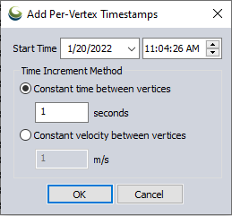
Add Per-Vertex Timestamps
Select this option to add timestamp values to each vertex in the list. The start time, or initial timestamp for the first vertex will need to be selected, and options to add timestamps for following vertices based on time or speed are available.
Display Times as UTC Rather than Local
For vertices with existing time data, such as from a GPX file, this option will control whether the times are displayed in UTC (Zulu) time or are converted to local time for display. If selected, the "Time" column header will be renamed to "Time (UTC)" and the values will repopulate accordingly.
Edit Timestamp
For vertices with existing time data, the time value can be edited. Selecting this option will allow you to alter the timestamp for the selected vertex and choose whether or not that impacts other time data values in the line based on speed or time.
Edit Speed for the Selected Leg(s)
For vertices with existing time data, the speed of the selected line segment can be edited, impacting the time value for following vertices.
These right-click context menu options require per vertex elevations:
Apply an Offset to the Selected Elevation
Add an elevation value to the existing vertex value. The units are displayed in the Feature Vertex list in the Elevation column label.
Apply a Scale Factor to the Selected Elevations
Multiply the existing vertex elevation by a number to scale the value.
Evenly Spread Elevations Between First and Last Elevation
The elevation values will be evenly spread along the length of the area feature to maintain a consistent slope from the first elevation to the last.
Interpolate Elevations to Replace 0 values
Replaces existing vertex elevations that are 0 with an elevation value to provide a consistent slope between the neighboring vertices. Distance to the neighboring vertices is factored into the interpolated elevation value.
Select Next Vertex in Line/ Area Feature
Choosing this will select the next vertex in the selected line or area feature, useful if all vertices in a feature need to be edited.
Select Previous Vertex in Line/ Area Feature
Choosing this will select the previous vertex in the selected line or area feature.
Remove Per Vertex Elevations from Selected Features
This option is available in the Digitizer menu or context menu under Vertex Editing. This will remove the elevations that have been applied to each vertex. It will convert the 3D feature back to a single elevation if there is an appropriate elevation attribute, or to a 2D feature.