
The Coordinate Geometry (COGO) tool creates line features based on distance and bearing, coordinate geometry or quadrant/ bearing/ distance notation. This is a powerful tool that can convert survey definitions and legal definitions of boundaries into vector features.
The  Create Distance / Bearing / COGO line tool is available from the Digitizer Toolset, or in the Digitizer menu or context menu under Create Area/Polygon Features.
Steps for using the COGO tool
1. Select the Create
Dist/ Bearing/ COGO Line tool to set COGO as the active cursor tool.
2. Click on the map at the starting location of the new line feature:

-
While selecting the start point for the line, the Snapping feature can be used to help align the line with existing features.
-
The starting location can be updated once the COGO dialog appears by using the Set Start Position button.
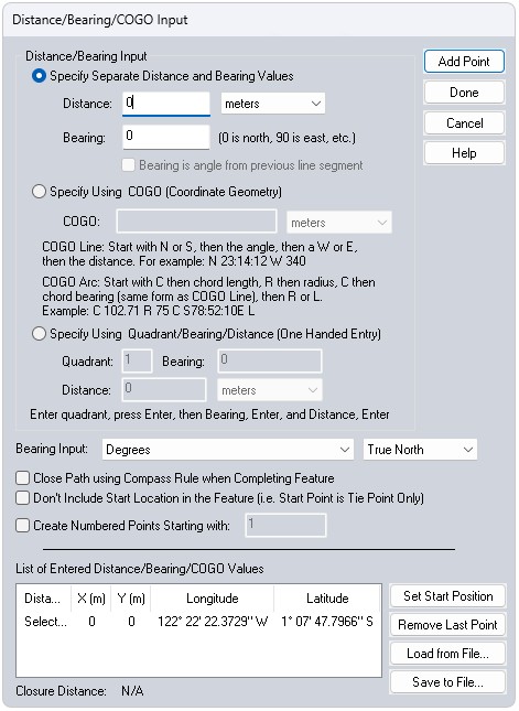
After selecting the starting location, the Distance/ Bearing/ COGO Input dialog will display, enabling entry of additional segments either as separate distance/ bearing values, as COGO (Coordinate Geometry) coordinates, or as a quadrant/ bearing/ distance value.
3. Select the desired method for entering segments, and press Add Point once the desired values have been entered. The added geometry can be visualized on the map as the coordinates are entered.
4. Once all of the points have been entered, press Done to complete the process and create the new line feature.
Specify Separate Distance and Bearing Values
Enter a Distance and Bearing value from the start point, then press the Add Point button to add the segment to the list at the bottom of the dialog. Repeat this for subsequent points until the feature is complete.
Note: Clicking on the map while the distance and bearing option is enabled will update the values in the Distance and Bearing field to match the clicked location.
To specify a bearing value relative to the previous segment, check the option Bearing is angle from previous line segment. A positive value for the Bearing will compute an angle clockwise relative to the previous segment. A negative value will compute an angle counter-clockwise relative to the previous segment. The check box can only be enabled after the first segment or point has been added.
Example
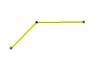
For the first segment, use Distance of 1000 m and Bearing of 0 degrees, and click the Add Point button.
Now put a check in the box next to Bearing is angle from previous line segment, enter 45 in the Bearing field and click Add Point.
You will see a new line at a 45 degree angle from the first line, and the list of Distance/Bearing values will include "1000 meters at 45°".
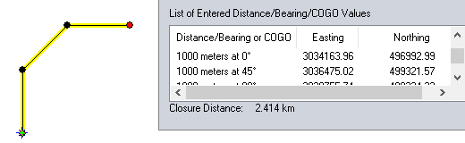
Leave the fields the same and click Add Point again.
Now Global Mapper will add a line at 45 degrees from the previous
segment, or 90 degrees from true north, and "1000 meters at 90°"
will be added to the value list.
Specify Using COGO (Coordinate Geometry)
To specify a line using COGO start from a N or S position, then specify a bearing E or W from that direction. Last enter the distance.
The first character of a COGO input string must be either the character 'N' or 'S' to indicate whether the bearing is relative to the north or south directions. After another space, the angle begins. The angle can be in any angle specification that Global Mapper supports, including degrees, degrees/minutes, or degrees/minutes/seconds. A space follows the angle, and is then followed by either the 'E' or 'W' characters. A space separates the bearing from the distance (which should be in appropriate linear units).
Use the following format:
N/S <DD:MM:SS or DD.DDD> E/W <distance>
Examples
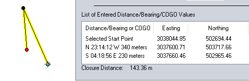
N 23:14:12 W 340
S 04:18:56 E 230
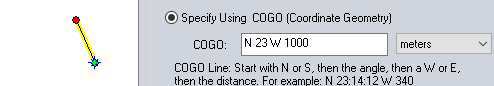
This segment heads 23° West of North, for 1000 meters.
To enter a COGO string that represents
an arc, the string format is as follows:
chord length is the length of the chord from the segment start point to the end point in the specified units.
radius is the radius of the arc in the specified units.
chord bearing uses the same form as the bearing in the COGO line.
direction is L (left turn, counter-clockwise) or R (right turn, clockwise)
The COGO Arc definition will be stored in the list in this same format.
The Easting and Northing will be the end point of the arc segment. When
the line feature is created, the COGO arc info will be used to generate
a polyline representation of the arc.
This format will also be used to store the
arc definitions in the text file.
Example
C 102.71 R 75 C S78-52-10EL
C - Chord length is 102.71
R - Radius is 75
C - Chord bearing is S78-52-10E
L - indicates Left turn
Specify Using Quadrant / Bearing/ Distance
For the Specify Using Quadrant/Bearing/Distance option, specify a quadrant value of 1 to 4, with 1 being the NE quadrant, 2 being the SE quadrant, 3 being the SW quadrant, and 4 being the NW quadrant. The bearing values are then east of the NS line for quadrants 1 and 2 and west of the NS line for quadrants 3 and 4.
One Handed Entry of Values
To achieve very fast entry of large collections of distance/ bearing of quadrant/ distance/ bearing values use the number pad and press Enter after each value. This will take the cursor to the next field and finally add the point when Enter is pressed on the last field. This will also take the cursor back to the first field to allow continuously adding points with only one hand.
Bearing Input Units
This drop-down menu allows users to specify what unit type will be used for Bearing Input values.
Unit options include: Degrees, DMS as DDDMMSS[.SS], DMS as DDD.MM, DMS as DDD.MMSS[SS], Mils (6400), and Grads.
Bearing source options include: True North, Magnetic North, and Grid North.
Options
Create Numbered Points Starting with - If this box is checked, then in addition to the line, a point is created at each vertex starting at the specified number and increasing by 1 for each point. The last number is remembered, if another line is created it will start at the next number by default.
If the option to Close Path Using Compass Rule when Completing Feature is enabled, all of the points will be adjusted using the compass rule to ensure that the shape is closed. The compass rule evenly distributes the shift required to close the shape to all vertices and is commonly used by surveyors.
Notes on Bearings
If the projection isn't oriented so that 'up' is also true north (most projected systems, like UTM, are not unless right at the projection center) a line of bearing 0 won't be straight up, but will be slightly skewed so that it points at the North Pole. A line of bearing 0 will be straight up in projections like Geographic or Mercator where true north is always straight up.
Notations will be saved after creating line features from the Create Distance/ Bearing /COGO Line tool. Notations can be viewed using the Feature Info tool and selecting the Notation button or the Add/Edit Notation in the Modify Feature Info dialog.
Example
List of segments entered into COGO:
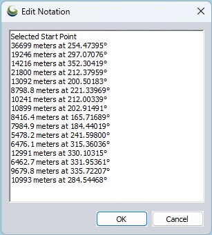
Once you have finished creating the point, users can view Notations via the Feature Info Tool of a feature, or via the Modify Feature Info tool.
For those unfamiliar with the notation for bearings: Picture yourself in the center of a circle. The first hemisphere notation tells you whether you should face north or south. Then you read the angle and either turn that many degrees to the east or west, depending on the second hemisphere notation. Finally, you move distance units in that direction to get to the next station.