The Rectify (Georeference) Imagery tool in Global Mapper adds spatial reference information to a file that does not initially have this information. Rectification (georeferencing) is the process of assigning geographic location, scale, and alignment to a file. This is done through the use of ground control points (GCPs) which can be entered manually or chosen from loaded reference data. While georeferencing is traditionally performed on raster data, the process can be applied to vector data as well. With Lidar data and 3D terrain models and mesh features, the rectification option will display a 3D Layer Control Points dialog, with options for adding 3D control points.
Rectification is common when working with paper maps which have been scanned and other non-georeferenced imagery. It can also be used for vector data created outside of a GIS or without any coordinate reference system information. It can also be applied on a layer that already has spatial reference, to create better alignment with control points.
After a file has been properly georeferenced, it will display in the correct location within Global Mapper. The initial rectification can always be modified. This is done by right-clicking on the layer in the Control Center and choosing RECTIFY.
Access the Rectification tool from the File menu > Rectify (Georeference) Imagery.... This option can load any supported file(s), including vector data. Loading an unreferenced raster file will automatically prompt with an option to rectify in the Select Position to Use dialog (shown below). To rectify an existing loaded layer, right-click on the layer in the Control Center and choose RECTIFY.
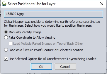
Image Rectifier Dialog
The Image Rectifier dialog is the heart of the image rectification process. This dialog contains everything that you need to rectify an image, from views of the image and reference data, to lists of ground control points, to a variety of ways to enter GCPs, to along with lists of ground control points, to an Options menu for advanced settings.
Steps for Georeferencing an Image
-
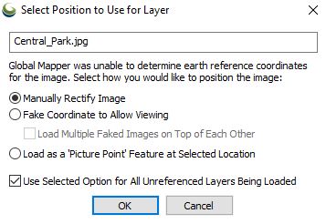
The Select Position to Use for Layer window will open when loading a non-georeferenced file in to Global Mapper. To rectify the file, choose Manually Rectify Image.
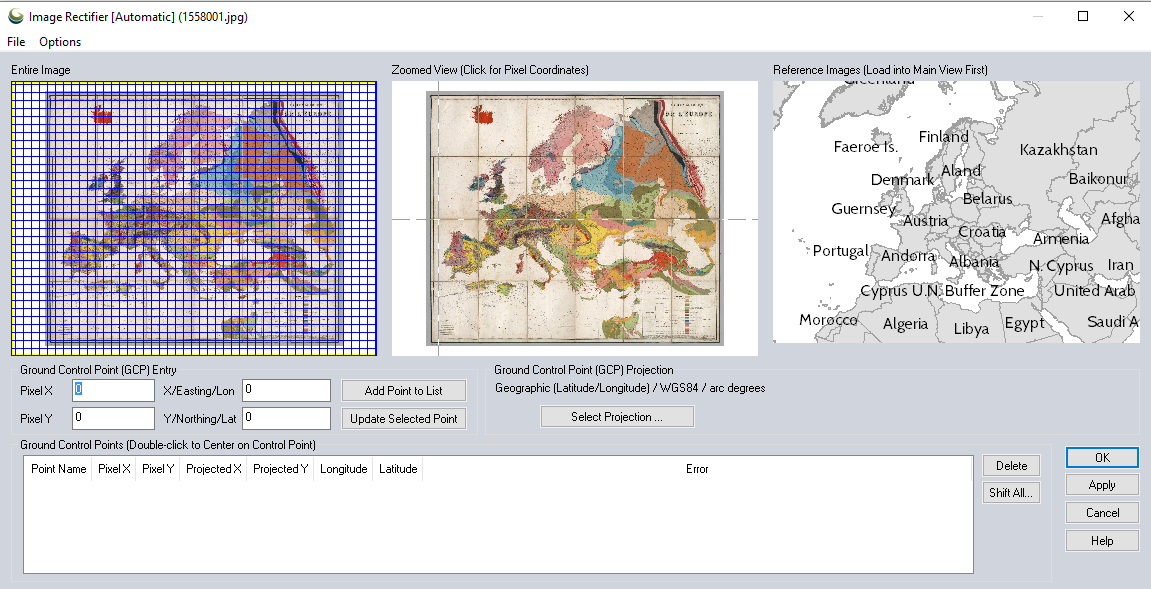
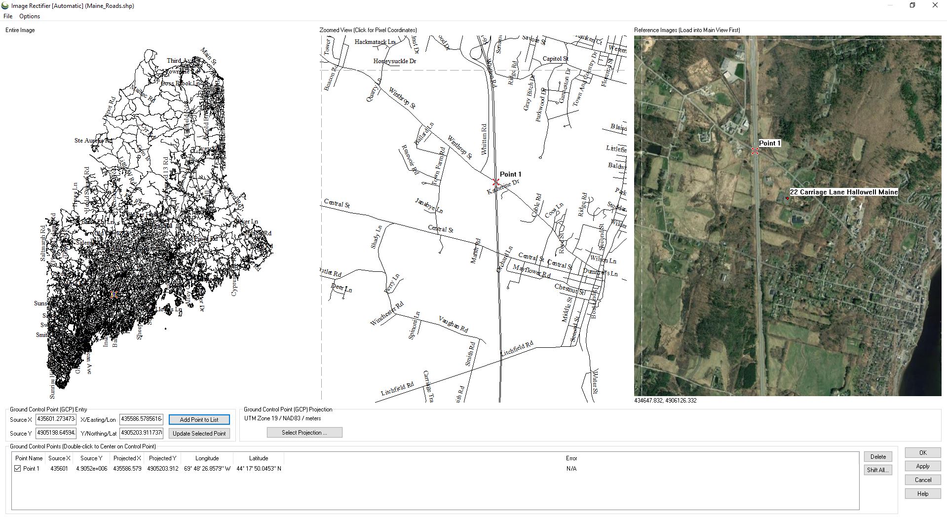
This will display the Image Rectifier window. The Entire Image view will show the entire file to be rectified. The Zoomed View will match that view initially, and the Reference Images view will show any reference data loaded into Global Mapper.
-
Optionally specify the projection to reference the data in by pressing the Select Projection... button.
-
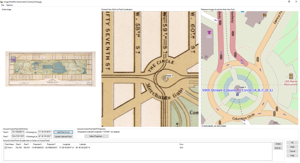
Select the location of the control point in the Zoomed View by left-clicking on the view. This will update the pixel values in the Pixel X and Pixel Y boxes, and place a point feature on the zoomed view. Then set the corresponding reference location, either by left-clicking on the Reference Images view, or by manually entering values in the X/Easting/Lon and Y/Northing/Lat boxes. Once the Pixel X, Y and reference X,Y values are correct press Add Point to List to add the point as the first ground control point in the Ground Control Points List.
In the below image, the first point was placed by zooming into a location on the non-georeferenced image in the Zoomed View, left-clicking to place a point, and then selecting the same location in the Reference Images view.
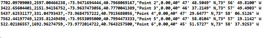
Points can be added from a GCP file as well. This is a comma delimited text file, with the data stored in the following order within a row: Pixel X, Pixel Y, Projected X, Projected Y, Point Name, Error, Longitude, Latitude. The file can be created in a text editor and saved with the extension *.GCP .
To load the GCP file, go to File > Load Control Points From a File. Once loaded, the points will now be visible in all three views as well as on the Ground Control Points list .

-
Complete these steps for each control point. The minimum number of control points required depends on the rectification method specified in the Options menu. The default Automatic method uses all control points, and therefore does not report an error.
-
To complete the process, choose OK. This will apply the rectification and close the window.
Choose Apply to apply the rectification but not close the window. This is useful when updating an existing referenced file.
Once back in 2D View, the georeferenced file will display on the map. Using Multi-View, the reference image and newly georeferenced file are displayed side by side, below.
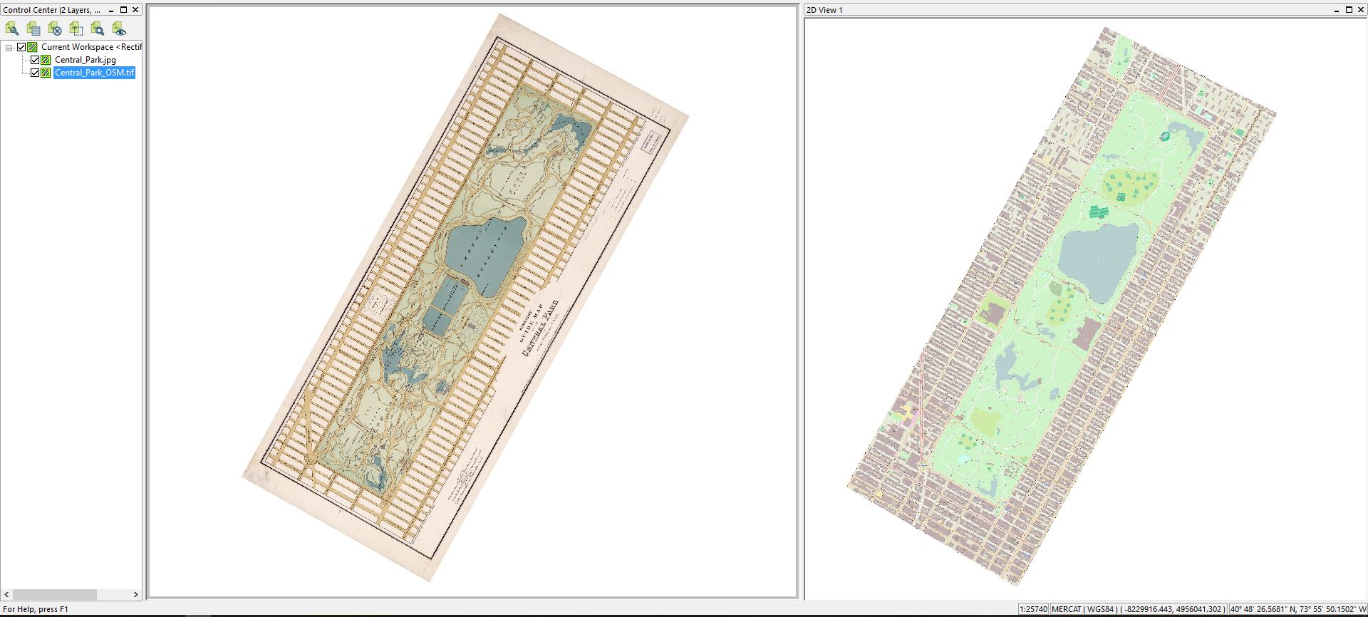
-
If necessary, right-click on the layer in the Control Center and choose RECTIFY - Modify Layer Position/Projection (Re-Rectify)
-
Global Mapper does not edit the original loaded data, and the rectification thus far will only be stored in the workspace. To save a correctly spatially referenced file, export the data to a new file using the File > Export menu or context menu for the Layer in the Control Center.
- Reference data can be loaded into the application in raster or vector format. Data from the Online Data tool can be utilized as well.
- When vector data is used as reference data, control points will snap to the vector layer when they are placed. Snapping can be disabled by holding down the Alt key when clicking.
- Holding down Shift will round the coordinates to the nearest 30 arc seconds, or 1000 ground units
- The Rectify (Georeference) Imagery tool can also be used to rectify vector data. This data can be first be loaded into the application with arbitrary coordinates or as a Pad Site. Once loaded the tool is accessed by right-clicking on the layer in the Control Center and choosing Rectify .
- If the data to be rectified has a coordinate grid on it, such as a scanned USGS DOQQ, those coordinates can be used as the basis of rectification. The location of the point is selected in the Zoomed View, and the real-world coordinate is then manually entered into the Ground Control Point (GCP) Entry field for X/Easting/Lon and Y/Northing/Lat as appropriate .
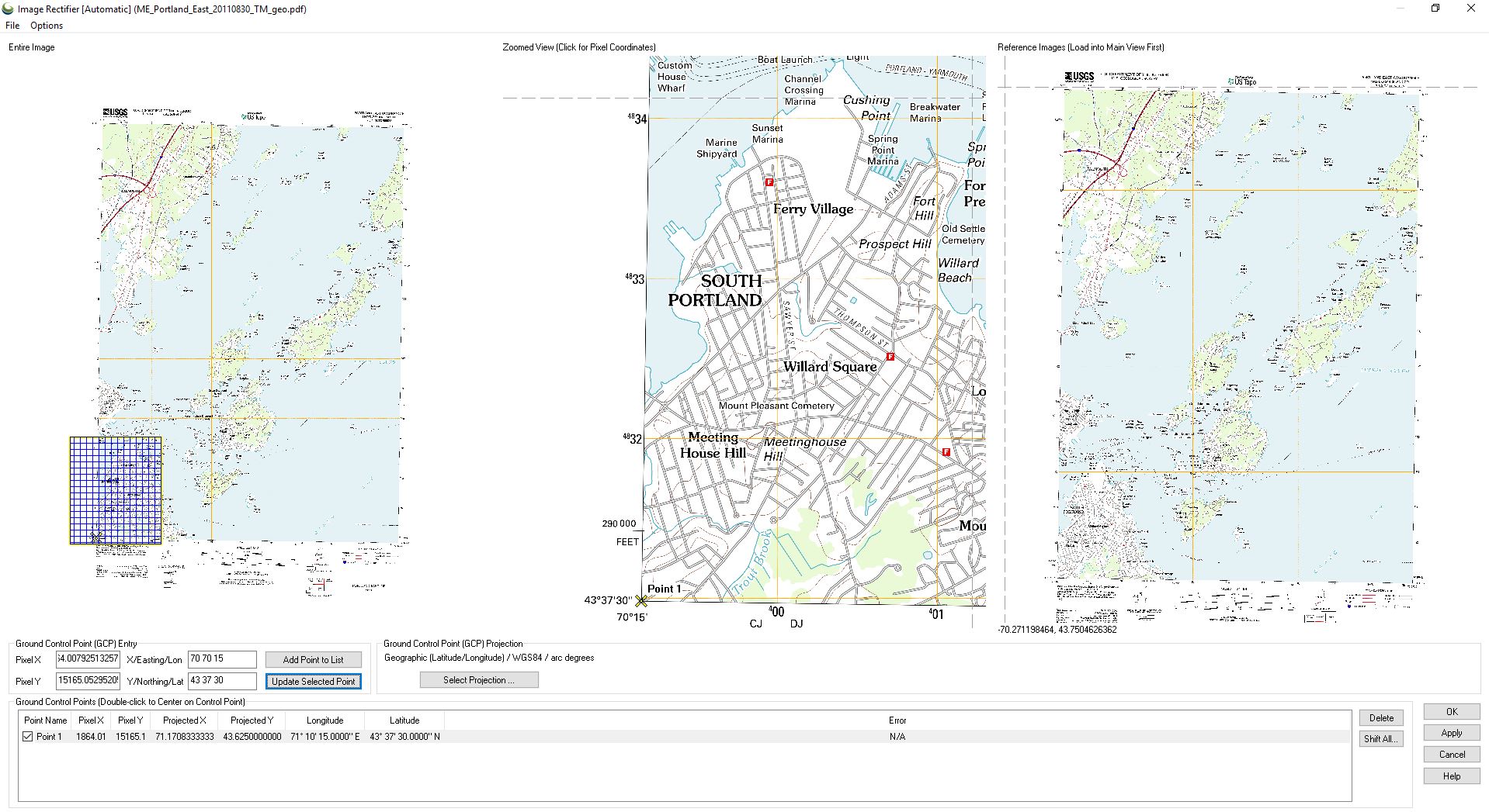
The image above is an example of a Topo image that is being referenced by manually entering coordinates. To reference an image with only two points, change the rectification method to linear in the Options menu.
If a rectification method is not specified, the linear method will be used by default when rectifying an image using two points. If the difference in X and Y pixel dimensions of the image exceeds 30 percent; then the Helmert method will be used.
The image above is an example of rectification of vector data. In this case the road data is being shifted to align with source imagery. This might have been vector data in a spatial format that needed adjustment, or vector data without spatial information.
Entire Image View
This window provides an overview of the image to be rectified. The grid pattern on the image reflects the extent of the Zoomed View. This can be adjusted by a mouse left-click or click and drag. As GCPs are added, they will be displayed as a red ‘X’.
Zoomed View
A zoomable view of the same image in which the control points will be added. Zooming is controlled using the mouse wheel or by clicking and holding with the left mouse button while dragging a box around the target area. The map can be panned up, down, left, or right using the arrow keys on the keyboard, or by positioning the cursor near the edge of the window and left-clicking when the arrow appears. Ctrl + right-click will re-center the image. Shift + click will automatically add the control point to the Ground Control Point list.
Reference Images
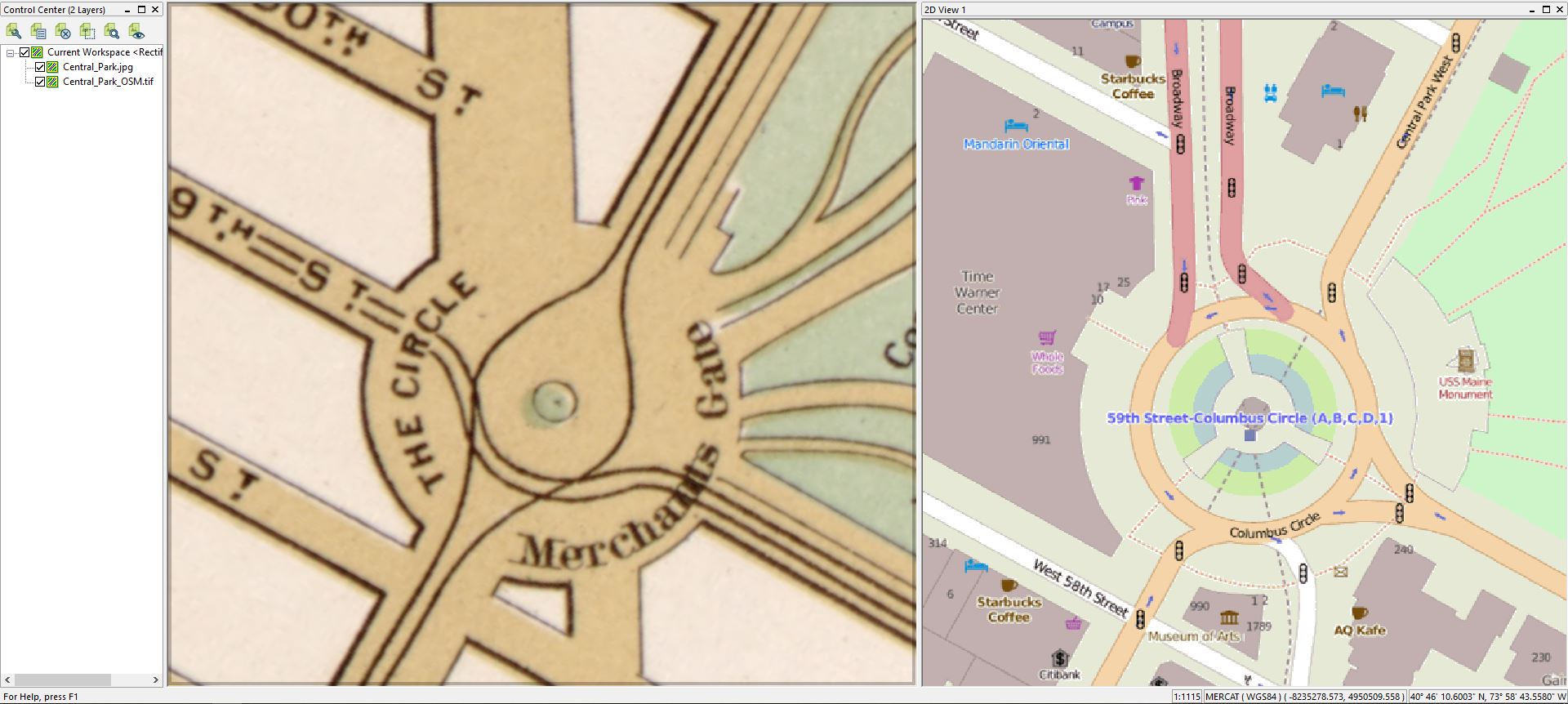
This window displays the contents of the main map window in which the ground control locations corresponding with the image control points are added. This view can be zoomed and panned in the same way as the Zoomed View window.
In Global Mapper 21.1 and later, the layer being rectified will automatically be hidden from the Reference Image view, regardless of its visibility in the Control Center.
Ground Control Point (GCP) Entry
If necessary, this section of the dialog box is used to manually enter the control point locations. Points are entered manually in pixel X,Y, followed by the corresponding real world coordinates. When choosing points by clicking on the imagery, these fields will populate automatically.
IMPORTANT: When manually entering the ground coordinates, they must be entered in the coordinate system indicated by the Ground Control Point Projection portion of the dialog, otherwise the results will be incorrect. If points are entered in a lat/lon format and a projected system is selected, the application will ask for confirmation of the format being used.
When entering latitude/ longitude coordinates, a number of shorthand formats are recognized for either decimal degrees or degrees minutes seconds (DMS). For example to specify South 45° 30" the follow examples would be correctly recognized:
- -45 30
- -45.5
- 45 30 S
- 45:30:0 S
Choosing Add Point to List confirms the values as a control point. The point will not be used for rectification until added to the list. This allows for fine-tuning of the positions.
The Update Selected GCP button (Alt +R) allows for the update of the coordinates associated with a previously entered GCP.
Ground Control Point (GCP) Projection
Define the projection of the ground coordinates as well as what projection the image will be natively treated as when rectified. The image can be reprojected later using the normal Global Mapper reprojection mechanisms. As mentioned above, it is important for the coordinates used to match the system which is chosen.
To control the default projection used, create a default_rectification.prj file in the User Data Folder. If present, the default rectification projection when opening the rectification dialog will be determined based on that file.
If the projection is changed when a list of Ground Control Points is already populated, it is necessary to specify how to apply the projection.
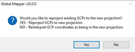
Select yes to transform the existing coordinates into the new projection. Press no to keep the coordinate values the same, and redefine them as part of the new coordinate reference system. The no option would be necessary, for example, when manually entering coordinates that do not match the listed GCP projection.
Ground Control Points List
This section of the dialog contains a list of all of the entered GCPs, including their name, pixel coordinates, ground coordinates, and the estimated error.
The error reports the root mean square error, and the error in the X direction and Y direction, in pixels for each GCP based on the current rectification method. The default Automatic method uses all control points in the equation, and therefore does not report an error unless there are more than 3 points, and one is deselected.
The checkbox next to each GCP specifies whether or not the point will be used in the rectification equation.
Double-clicking an item in this list will cause the Zoomed View to recenter on the GCP and will fill in the Ground Control Point Entry section with the pixel and ground coordinates of the selected GCP, allowing for easy updating of GCP locations. Keyboard shortcuts Alt + Z and Alt + Q provide an alternate way toggle through the list of GCPs.
Shift All allows for all points to be shifted a fixed distance.
Delete will delete the highlighted Control Point(s) in the list.
Completing the Rectification Process
Once all GCPs have been entered, OK will apply the rectification process and close the tool. Apply will run the rectification process, without closing the window, so that the result can be previewed in 2D View.
Batch Rectification
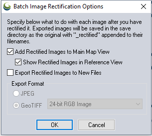
Batch rectification can be completed by selecting Rectify (Georeference) Imagery... in the File menu.
This tool allows for multiple images to be rectified. This tool allows for the options of ‘Add Rectified Images to Main Map View, ‘Show Rectified Images in Reference View, and Export Rectified Images to New Files.
Each image will then be rectified as outlined in the steps above. Once rectified, an image will get added to the Reference Images view in the Image Rectifier dialog, to be used to select GCPs for subsequent images if appropriate.
If Export Rectified Images to New Files was selected, the files will be written after ALL of the selected files have been rectified. All newly rectified files will be created in the same directory as the original images with '_rectified' appended to the file name. The original imagery will remain intact and unchanged.