Measure/ Units Configuration
The Measure/ Units section in General Configuration contains settings relative to units and methods used in the Position Display in the bottom bar of the application, in the measure tool, and during feature calculations. Many of these options were previously available in the Measure Tool right click context menu. For vertical units see Vertical Options.
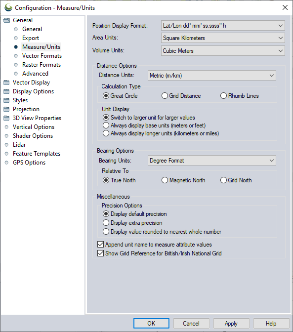
Access the Measure /Unit Configuration by selecting the  Configuration button from the File Toolbar or Tools menu, and navigating to the Measure/ Units section in the General folder.
Position Display Format
This setting controls the format of the cursor latitude/ longitude position display in the status bar. Choose from the following options:
- Lat/Lon dd.dddddddd° h (Decimal Degrees with heading N,S,E,W)
- Lat/ Lon +/-dd.dddddddd (Decimal Degrees with +/- prefix for quadrant)
- Lat/Lon dd° mm' ss.ssss" h (Degrees Minutes Seconds with heading N,S,E,W)
- Lat/Lon dd° mm.mmmmm' h (Degrees Decimal Minutes with heading N,S,E,W)
- MGRS/USNG (Military Grid Reference System/ U.S. National Grid)
Area Units
This setting controls what units area measurements will be calculated in using the Measure Tool or when creating new features with the Digitizer Tool or adding measurements as attributes.
Volume Units
This setting controls what units volume measurements will be calculated in when using the Measure Tool or when calculating volumes of existing features with the Digitizer Tool.
Distance Options
Distance Units
This setting controls what units that distance measurements will be displayed in the Measure Tool and when creating new features with the Digitizer Tool, as well on the Distance Scale bar. Choose from:
- Metric (m / km)
- Nautical (ft / nm)
- Statute (ft / miles)
- Chains (chains / miles)
- Yards (yards / miles)
- International Feet (ft / mi)
- Varas
- Rods
Calculation Type
Specify the method of distance calculation.
Note: If a Grid Measurement is selected for use with a Geographic projection, Global Mapper calculates a 'degree to meters' conversion factor in the longitudinal direction based on the central latitude of the points the length is between and uses a constant value based on the ellipsoid semi-minor axis for the latitudinal distance.Great Circle
Any measured distances will use the great circle distance, which is the shortest path along the surface of the earth's ellipsoid between the two points. Any drawn paths will be along the great circle path. Typically you won't notice a difference for short distances, but will for longer ones.
Grid Distance
Any measured distances will use the distance as calculated in the Cartesian XY coordinate system of the current projected system. Any drawn paths will be straight lines between the start and end point. This can result in inaccurate distances for long measurements or when working in projection systems with high levels of distortion.
Rhumb Line
Any measured distances will be drawn along the rhumb line if possible, which is a line of constant bearing between the start and end point. Rhumb lines are often used in navigation so that a constant bearing can be maintained. A rhumb line will be a straight line in the Mercator projection. Any drawn paths will also be along the shortest rhumb line path between the start and end point.
Unit Display
Switch to larger unit for larger values
Length and perimeter measurements will use the larger distance unit for larger areas.
Always display base units (meters or feet)
Length and perimeter measurements will always use the base unit.
Always display longer units (kilometers or miles)
Length and perimeter measurements will always use the larger unit of measure.
Bearing Options
Bearing Units
Specify the units of bearing from the following options:
- Degree Format
- Two Directional Survey Method
- Mils
- Grades
Relative To
Specify the reference for the reported bearing value from the following options:
True North
Any measured bearings will be reported relative to True North. This means that a bearing of 0° will point directly at the North Pole and bearings of 180° will point directly at the South Pole.
Magnetic North
Any measured bearings will be reported relative to Magnetic North. This means that a bearing of 0° will point directly at the magnetic North Pole rather than the geographic North Pole. All other bearings are relative to that, so a bearing of 180° is exactly away from the magnetic North Pole. The magnetic North Pole slowly meanders around, but is not coincident with the geographic North Pole.
Grid North
Any measured bearings will be reported relative to Grid North. This means that a bearing of 0 will point directly up on the Y axis of your current display projection (to the top of the screen assuming you don't have any rotation enabled), 90° will be directly to the right along the X axis, etc. If your projection is one that is orthogonal to the latitude/ longitude grid, like Geographic or Mercator, the cardinal directions (0°, 90°, 180°, and 270°) will be the same, but in between could vary due to scale differences.
Miscellaneous
Precision Options
Display default precision
The precision displayed in feature measurements is reported relative to the map scale.
Display extra precision
Measurements will be reported in extra decimal precision.
Display value rounded to nearest whole number
Measurements will be rounded to the nearest whole number for the displayed unit.
Append unit names to measure attribute values
Measurement values that are added to features as attributes will include unit specification in the attribute text.
Show Grid Reference for British/Irish National Grid
When enabled the current projection coordinates will display in reference to the projection grid. When disabled coordinates will display as northings and eastings.