DWG
Load DWG
Global Mapper can load DWG files from Autocad 2018 and earlier. The color / style, feature description, and name will be derived from the file. To see sublayers in the file, see Split
Into Separate Layers Based on Attribute Value using the <Feature Description>.
DWG files can also be loaded as custom point symbols. See Custom Symbol Configuration.
Export DWG
The Export
DWG command allows the user to export any loaded vector data sets to an
AutoCAD® Drawing (DWG™) format file. *
TheExport DWG command can be
accessed through File>Export
Vector/Lidar Format...Select Export
Format. Individual layers can also be exported from the Control Center by right-click on the layer and going to Layer > EXPORT. Multiple files can be batch converted to and from the format from the Batch Convert/Reproject tool.
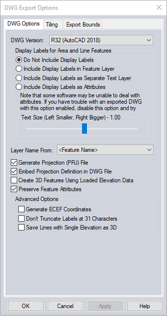
When selected,
the command displays the DWG Export Options dialog (pictured below) which
allows the user to set up the export. The dialog consists of a DWG Options
panel, a Tiling panel, and an Export Bounds panel which allows the user
to set up the portion of the loaded vector data they wish to export.
DWG Version
The DWG Version
section allows you to select which DWG version to create. Select from the following versions:
- R12
- R13
- R14
- R15 (Autocad 2000)
- R18 (Autocad 2004)
- R21 (Autocad 2007)
- R24 (Autocad 2010)
- R27 (Autocad 2013)
- R32 (Autocad 2018)
Display Labels for Area and Line Features
The Display
Labels section controls if feature display labels are
included in the DWG files and, if so, whether they are represented
as TEXT entities in their own layer (called FEATURE_LABEL) or as DWG attributes.
The default is to have them included as attributes associated with each
feature. As some software packages cannot handle attributes in DWG files, it may be necessary to switch to a different option (with the associated loss
of information) to get exported DWG files to work with some software
packages. To have rotated labels running
along the line associated with them, use the option to Include
Display Labels as Separate Text Layer.
Layer Name From
The Layer
Names section controls how the layer names used in the exported
DWG file are generated. Choose any of the available attributes as the layer name. The attribute selected as the Layer Name will be used as the <Feature Description> attribute in the generated export.
If <Feature Name> is chosen as the display label, any features that do not have a display label will use the feature
description as the layer name in the exported file.
Other Options
Generate Projection (PRJ) File
If selected,
the Generate Projection (PRJ) File option causes a projection file describing
the ground reference system of the DWG file to be generated in addition
to the DWG file itself. The PRJ file will have the same name as the DWG
file with the .prj extension.
Embed Projection Definition in DWG File
If selected this option will write the projection definition for the data into the generated DWG file. Global Mapper will warn users if the current workspace projection cannot be translated into a coordinate system definition supported in DWG format.
Create 3D Features Using Loaded Elevation Data
If selected,
the Create 3D Features Using Loaded Elevation Data option will cause any
underlying elevation data (like DEMs) to be used to retrieve elevation
values for 2D features being exported and generate new 3D features in
the exported DWG file. The units used by the elevation values are determined
by the Elevation Display/Export Units setting in the Configuration dialog.
Preserve Feature Attributes
Attach attributes to the file. Each feature will be exported as a BLOCK, with an associated INSERT added as a block reference. The attributes will be attached to the INSERT entity, and can be viewed and edited in AutoCAD® using the Attribute Editor.
Generate ECEF Coordinates (Advanced Users Only)
If selected,
the Generate ECEF Coordinates option will cause the exported DWG file
to use Earth-Centered Earth-Fixed (ECEF) XYZ coordinate values rather
than XY values in the current export projection.
Generate Zero-Width Lines
If selected,
the Generate Zero-Width Lines option causes and line features created
in the DWG file to be marked as having zero width. Use this option if
you intend to use the resulting DWG file with a product such as MicroStation
which has problems with lines of non-zero thickness.
ADVANCED: Don't Truncate Labels at 31 Characters
The settings will allow labels to be longer than 31 characters.
ADVANCED: Save lines with single elevation as 3D
This setting will create 3D line features for lines with an elevation attribute rather than per vertex elevation values. Contour lines, for example, typically have a single elevation value stored in an attribute, and not per vertex elevation values.
Note: If features of the TIN Face Area area type, including 3D mesh faces, are exported they will be exported
as 3D Face features in the generated DXF file rather than 3D polylines,
allowing you to easily get a usable TIN surface for use in other applications,
like 3DS Max.
* AutoCAD is a registered trademark of Autodesk, Inc., in the USA and other countries. DWG is the native file format for Autodesk’s AutoCAD® software and is a trademark of Autodesk, Inc.
Format Updates
Below is a summary of recent changes to DWG format support:
| 23.0 |
Option to include projection definition in DWG and DXF exports. [#GM-11957] |
| 23.0 |
Added support for import of AutoCAD 3D solid entities as mesh features. [#GM-1468] |
| 22.0 |
Updated DXF and DWG exports to handle 3D models (meshes). Each triangle in the mesh is exported as a 3D area feature. [Item #GM-11345] |
| 22.0 |
Include color from GM point symbols when exporting to DWG and DXF.Read point color when importing DWG and DXF.[Item #GM-5606] |
| 21.1 |
Improved display of filled areas in SOLID entities when loading DXF and DWG files.[Item #GM-5955] |
| 20.1 |
Applied extrusion vector when computing points for a polyline with bulges during DWG/DXF import.
|
| 20.1 |
Updated DWG/DXF exports to support using any attribute value as the Layer value rather than just special values like .[Item #25922]Change History
5 - Minor New Feature False |
| 20.1 |
Added support for using any supported vector format as a custom point symbol, including DWG, SHP, and GMP files. Also improved automatic scaling of vector formats used as a point symbol when the raw coordinates are very small or very large. |
| 20 |
[Scripting] Added support for a
new EXPORT_SINGLE_ELEV_2D parameter for EXPORT_VECTOR script command to
specify that line features with a single elevation (like contours) should be
exported as 2D polylines with a single elevation rather than 3D polylines.
This applies to DXF and DWG export. |
| 19.1 |
Added support for importing and
exporting AutoCAD 2018 DWG files |
| 19.1 |
Updated DWG export to place line
attributes before the line feature geometry rather than after to match what
is done with area and point features. |
| 18.2 |
Added the ability to export
feature attributes to DWG and DXF files. |
| 18.2 |
Automatically recognize code
page (character set/language) when importing DXF/DWG files so that labels
will be properly displayed automatically regardless of the system language.
Also write out the appropriate code page when exporting DXF/DWG files. |
| 18.2 |
Modified behavior of DXF/DWG
entities with color 7. Rather than always being white it is now black if the
background color is light and white if the background color is dark. In
addition, the color index 0 is no longer used on export as it is not valid. |
| 17 |
[Scripting] Added support for
specifying the attribute to use for the layer name in DWG/DXF exports using
the LAYER_NAME parameter for the EXPORT_VECTOR script command. |
| 17 |
[Scripting] Added support for
specifying the version of DWG to export using the VERSION parameter for the
EXPORT_VECTOR script command. |
| 17 |
Updated DXF and DWG export when
exporting feature labels as attributes to place the attribute at the
appropriate Z (elevation) rather than at 0.0. |
| 16.2 |
Improved export of display
labels to DWG files. Now text color and alignment is maintained and
multi-line text is properly aligned. |
| 16.1 |
[Scripting] Provide more options
for label export to DXF/DWG files using the EXPORT_VECTOR command. Now the
EXPORT_DWG_LABELS/EXPORT_DXF_LABELS parameters support exporting features
labels as attributes, separate points on the features’s layer, or separate
points on a label layer. The existing Yes/No support still works as before. |
| 16 |
Added support for using PRJ
files for DWGs. |
| 15.2 |
Added option to DWG export to
control whether or not 2D lines with a single elevation (like contour lines)
are saved as 3D lines or 2D lines with an elevation. |
| 15.2 |
Added support loading ELLIPSE
entities from DXF and DWG files. |
| 15.1 |
Further rendering improvements
for complex DXF/DWG files, including fixing problems with lines that are too
wide and better support for multi-line text. |
| 15.1 |
Made DWG exports of 2D line
features create 2D polylines rather than 3D polylines. |
| 15 |
Updated DXF/DWG import to set
the default view to the extents specified in the file rather than just
showing everything. This eliminates the default view of a bunch of extra
stuff and not the core data. |
| 15 |
Added additional options to
DWG/DXF export for choosing what information about a feature to create the
layer name from (i.e. description/type, name, layer name, etc.). |
| 15 |
Greatly improved display of text
loaded from DWG/DXF files, including getting font names and proper alignment
in many cases. |
| 15 |
Made 3D Tin Face areas loaded
from DXF/DWG files use the brush style for the type from the Area Styles tab
of the Configuration dialog rather than always filling the TIN areas. |
| 15 |
Added support for new text
alignments that align text with the baseline of text rather than the middle
of text. This is not automatically used when loading DXF/DWG files that
specify that alignment. |
| 14.2 |
Added support for exporting
point clouds to DXF and DWG format files. |
| 14.1 |
Added support for importing and
exporting DWG 2013 files. |
| 13.1 |
Updated DXF and DWG exports to
have new labeling option to include labels in same layer as area and line
features that they come from rather than generic FEATURE_LABELS layer. |
| 13 |
Added options to DWG and DXF
exports to allow exporting labels longer than 31 characters. |
| 12 |
Made batch conversion to DWG
files use the DWG version last selected on the DWG export dialog. |
| 11.2 |
Added support for GeoDXF and
GeoDWG files (DXF/DWG positioned with WLD file). |
| 11.2 |
Added option for users to choose
which DWG version to create when exporting a new DWG format file. |
| 11.1 |
Added support for reading DWG
2010 format files. |
| 11.1 |
Allowed cropping DWG, DXF, and
several other exports to a selected crop area. |
| 11 |
Added support for exporting
loaded vector data to DWG format files. |