Map Layout Editor Menu Options
Many of the below menu options are also available by right-clicking on the layout or on a selected element.
Use the options in the File Menu to manage map layout file types.
New Layout... Opens the Map Layout Preview Options. Resets the Map Layout Preview, removing any existing elements.
Open Template... Opens a previously saved Map Layout Template. Saves the current template, or creates a new one if the current layout has not been saved as a template.
Save Template - Saves the current Map Layout Template or Map Layout in a new Map Layout Template file (.gm_mapTemplate).
Save Element Block - With an element block selected, choose to save this layout of map elements in a Map Element file (.gm_mapElement). Useful for title block or metadata information that needs to be applied to multiple layouts.
Load Element Block - Opens a previously saved element block from a Map Element file (.gm_mapElement) and loads it into the current page layout.
Create a MapBook... Divides the data into multiple pages using a template to set the map elements on each page. See more information about creating a MapBook
Create Feature Mapbook... Generates multiple pages using a template centering on each of the selected vector features. See more information about creating a Feature MapBook
Print... - Brings up the Print dialog (below) to print the current Map Layout Preview.
Print to File... - Allows saving the layout to an image file (BMP, JPG, PNG, geoTIFF). Also enter the image file name. Note that even though the output will go to a file, select a printer and press Print on the Print Options dialog that are displayed after clicking OK.
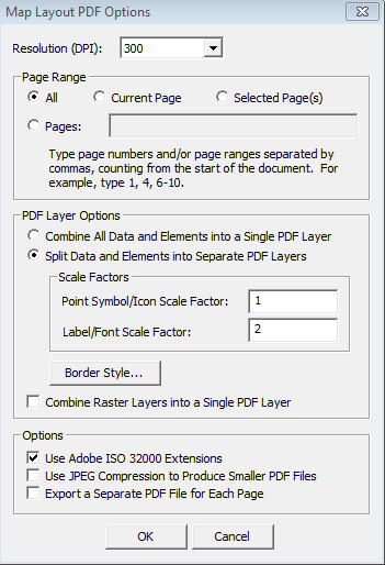
Export to Geospatial PDF... -
- Resolution (DPI) - Pick one of the Dots Per Inch (DPI) options from the list to specify the output resolution.
- Page Range - specify the page(s) to include in the pdf.
All Export all pages in the current map.
Current Page Export the currently displayed page to the PDF file.
Selected Page(s) Export the pages that are currently selected in the Tile Name pane.
Pages Export the pages as indicated in the associated edit box. The user can specify one or more page numbers or page ranges (separated by a dash), separated by commas. For example, “1, 3, 5-9, 12” would export page 1, page 3, pages 5 through 9, and page 12.
- PDF Layer Options
Combine All Data and Elements into a Single PDF layer- this setting will create a flattened PDF.
The resulting PDF will have a single layer containing all of the elements. Note that when this is checked, the scale options will have no effect.
Split Data and Elements into Separate PDF Layers - This setting will create a multi-layered PDF where different layers in the map could still be controlled (made visible) independently. This also creates a larger file size
Point Symbol/Icon Scale Factor - Specify a scale factor to make point symbols larger or smaller in the output PDF.
1.0 is the default size, and the value represents a multiple of that, (i.e., 2.0 makes point styles twice as big).
Label/Font Scale Factor - Make text larger or smaller, similar to the Point Symbol scale factor. This applies to text in the map (labels, etc.), and not to text that is in Map Layout Elements (legend, scale, etc.).
- Border Style... - When clicked, this button will display the Select Line Style dialog, and the user can specify options for the border style. The border lines can be solid, dotted, or dashed, and have color. The Border Style... button will be disabled when the "Combine All Data and Elements into a Single PDF Layer" option is checked.
- Combine Raster Layers into a Single PDF Layer - This setting will flatten all imagery and terrain data into a single layer.
- Use Adobe ISO 32000 Extensions - When this is checked, the Adobe ISO 32000 extensions will be used to georeference the map view element. If it is not checked, the default (formerly TerraGo) georeferencing method will be used.
- Use JPG Compression to Produce Smaller PDF Files- When this option is checked, images written to the PDF will be compressed, thus producing smaller PDF files.
- Export a Separate PDF File for Each Page - This option instructs the Map Layout Editor to create one PDF file per page instead of a single, multipage PDF file containing all of the pages.
Export to PDF as Mosaic... This option allows for chopping a map layout up into multiple pages. It is designed for printing large layouts on a smaller sheet size and stitching back together. See more information about creating a Mosaic here.
The Map Layout Editor Preferences dialog will be displayed. The dialog contains the following options:
Display Units:
Use units from the paper size definition as display units - When this radio button is selected, the units for the rulers, margins, and element properties such as size and position will be displayed using the unit of the currently selected page size.(This is the default).
Use this unit as the display unit - When this radio button is chosen, the unit selected in the drop-down menu will be used when displaying the rulers, margins, and element properties such as size and position. When this button is not selected, the drop-down menu will be disabled.
Note: This option does not apply when editing a Custom Page Size definition. In that case, the page size units will always be used.
Map Layout Index - This setting displays a rectangular frame within the 2D map view representing the extent of the Map View Element on each layout page.
Page Names - Allows specifying a prefix for automatically named pages in the layout.
These settings apply to all workspaces.
User Interface:
Snap Elements on Drag - Enables the ability to automatically snap adjacent map layout elements together using drag-to-snap. The element will snap to the closest middle point or corner of the adjacent side. Elements with invisible borders, such as both arrows, can snap to other features, but cannot be snapped to.
Use the options in the Edit Menu to edit selected map layout elements, to save map layout elements to the clipboard, to use them from the clipboard or to remove elements from the map layout.
Copy - Copy the selected element(s) to the clipboard.
Paste - Paste an element definition from the clipboard. Note: the user can not copy and paste the Map View Element.
Delete - Delete the selected element(s) from the layout.
Undo - Undo the last change to the map layout. The editor keeps track of all changes made since the editor was started, a new layout was created, or a template was applied. Creating a new layout or applying a template can not be undone.
Redo - The Redo function reverses the most recent Undo operation. The editor keeps track of Undo operations until a new change is made in the editor. At that point, the list of available Redo operations is cleared.
Undo and Redo apply to the following types of changes:
- Add element
- Delete element
- Change element properties
- Resize element
- Move element
- Reorder elements
- Change page margin
- Change page background color
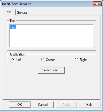
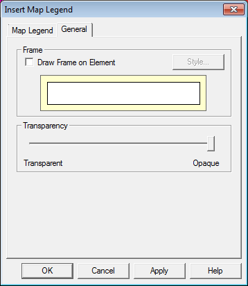
Use the options available in the Insert Menu to add new Map Layout Elements to the map layout, and to define the Properties unique to the element type. All Insert<Element>... dialogs below contain a General tab, where a frame can be added for the element and a frame style defined. This includes setting a background fill for the element. Transparency/ Opacity may also be set for both the element itself and the frame, respectively. Inserted elements will appear at the center of the layout page. Once inserted they can be edited, re-sized, and repositioned on the page.
Inserts a new Elevation Legend element into the Map Layout, once selected the Insert Elevation Legend dialog will appear (below).
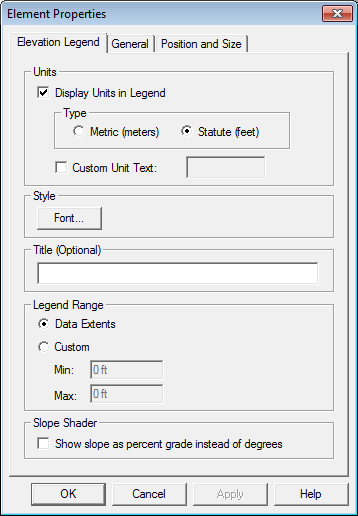
In the Units section, specify if legend units should display in Metric, Statute, or custom units.
In the Style section, you can select a font to use for the elevation legend, and set a title for the legend.
In the Legend Range section, if the elevation range you would like to use for the legend varies from the range of the data, you may specify a Custom elevation range. The units for the custom elevation range will be based on the units selected above.
If the elevation layer is using a Shader based on slope, you can check the option Show slope as percent grade instead of degrees to display a legend showing percent change, rather than a change by degrees
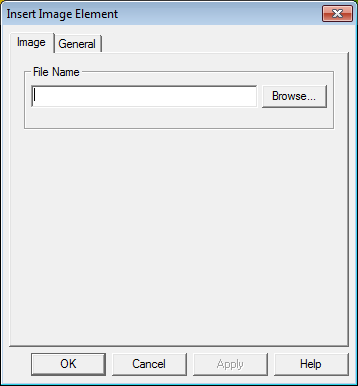
Inserts a image as a new image element into the Map Layout, once selected the Insert Image Element dialog will appear, allowing you to browse to an image file (JPG, GIF, PNG, TIF, EMF) and load it as an element to the map layout.
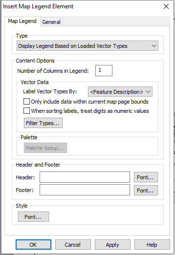
Inserts a new Map Legend element into the Map Layout, once selected the Insert Map Legend dialog will appear (below).
Select a legend Type from the following options:
- Display Legend Based on Loaded Vector Types - To create a legend based on loaded vector features.
- Display Legend Based on Color Palette - To create a legend based on the color palette of loaded raster data.
- Display Legend Based on Vector Types and Palette - To create a legend from both loaded vector features and a color palette.
Content Options
Under Content Options set up labels for the features or the icons to display in the map legend.
Specify the number of columns in the legend. The default is 1.
In the Label Vector Types By: drop-down menu choose to label vector features by Feature Description, Feature Layer Name, Feature Name, or Feature Type. Vector feature attributes for loaded data will also appear on the drop down menu.
Additional options are available for the sort and bounds settings.
Check Only include data within current map page bounds to only display vector types in the legend if they appear on the map layout.
Select When sorting labels, treat digits as numeric to sort numbers by quantity rather than alphabetical order. For more information see Map Legend Configuration
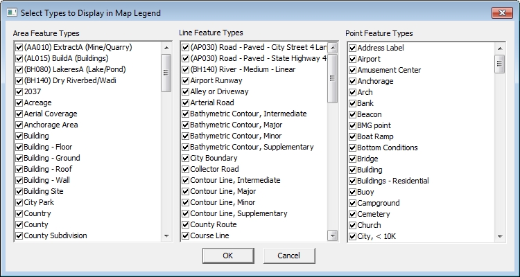
Click Filter Type to filter which Area, Line, and point Feature Types you would like displayed on the legend.
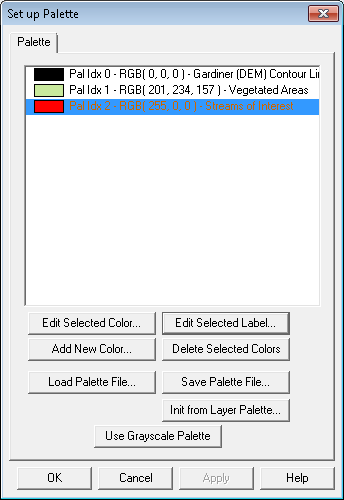
Please note that if 'Display Legend Based on Color Palette' is selected, the select vector attributes drop-down menu will be disabled. Specify the number of columns for your legend and if you selected one of the two legend Types that support a color pallet, click the Palette Setup... button to access the Set up Palette dialog (shown to the right).
In the Set up Palette dialog , it is possible to Edit existing colors, add new colors, use a grayscale palette, or load a palette file (.pal, .clr, .cpt, .smp ,.act, .tbl, .lut, .txt). Use the option to 'Init from Layer Palette File...' if you would like to use a color palette from another layer in the workspace, this is helpful if you have inserted an Image Element of another layer or map.
Use the Header and Footer section to add additional information about your legend or feature classification scheme, under the Style section select a font, background color, or to add a border to the legend. The font selected in this section will be used for the feature class labels in the legend.
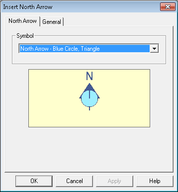
Inserts a new North Arrow element into the Map Layout, once selected the Insert North Arrow dialog appears. Use the drop-down menu on the North Arrow tab to select a symbol, on the General tab are options to add a frame, select a frame style and adjust transparency. This is a dynamic element and will adjust according to changes in the map layout orientation.
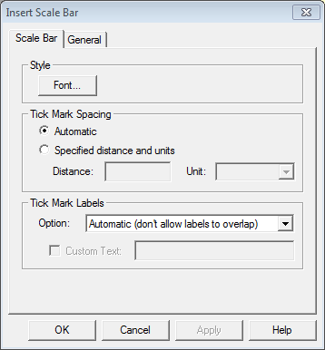
Inserts a new Scale Bar Element into the layout. This is a dynamic element and will adjust according to changes in the map layout definition (bounds or scale). Use the font option to setup the Style for the scale bar. The distance units used in the scale bar will be derived from the Distance Measure Units specified in the workspace Configuration dialog.
Select Tick Mark Spacing from the following options:
- Automatic - this is the default
- Specified Distance and Units - Customize the units and length of the scale bad. When this is selected the distance and units fields will be enabled, and the user must specify values for both.
Select Tick Mark Labels from the following options:
- Automatic (don't allow labels to overlap) - this is the current behavior and default
- Label all ticks (regardless of whether or not the text overlaps)
- Label every 2nd tick (regardless of whether or not the text overlaps)
- Don't label the tick marks (allows optional custom text to replace the labels)- When this option is selected, the Custom Text check box and entry field will be enabled. If the user checks the box next to Custom Text, he must also specify some custom text. The text will be displayed below the scale line. Note: Custom text will be displayed once, not per tick.
Inserts an Inset Map to display the 2D workspace, the 3D view, or the Path Profile view. The inset map will inherit the position and scale from the currently open relevant workspace or viewer.
The inset map is a static image, and will not automatically refresh when changes are made to the original viewer. To refresh the map, open the element's Properties and under the Image tab, check the Update Insert box to overwrite the existing map image with a new one, and click OK. This manual setting allows you to set the map, then not worry about accidentally changing anything when editing the main map.
-
Path Profile - inserts a static snapshot of the current Path Profile viewer. A profile must already been drawn for this feature to function. The snapshot takes the size and scale of the current path profile view into account. Make all edits to the path profile viewer, including adjusting the height and width of the viewer.
-
2D View - inserts a static snapshot of the primary workspace's current perspective.
-
3D View - inserts a static snapshot of 3D Viewer's current perspective including settings like perspective, background, and vertical exaggeration. If the 3D viewer is not currently open, a top down perspective will be used.
Select multiple map elements to see this option in the Insert menu. This creates a new Group element that incorporates the currently selected elements.
Prior to selecting this option, use the cursor + CTRL key to select the elements in the map layout that you would like to group. Grouping elements retains the respective elements' relative position to one another, and allows you to align grouped elements together.
Once elements are selected and Group Elements... is selected from the Insert menu the Group Element Options dialog will appear.
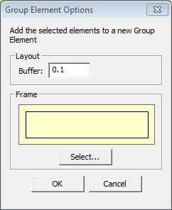
Specify the Buffer distance you would like for grouped elements and use the Select... to set an Area Style if you would like to set a frame for the grouped elements.
Once added, any of the element properties defined in the above setup dialogs can later be edited by selecting the element with the mouse cursor and right-clicking to access the edit element options or by clicking the Properties... button with the element selected in the Map Element Control Center.
To completely remove a group select the group from the map layout, and choose this option from the insert menu, or right-click to the insert sub menu and choose Ungroup Selected Element(s)
Ungroup Contained Element(s) - To remove an element(s) from a group, select one or more elements in the group, then choose this option from the Insert menu, or right-click on the element, and choose it from the insert sub-menu. Ungroup Selected Element(s) will remove the selected element(s) from the group.
Align to Margin – Moves the currently selected elements so they align with the layout margins as follows:
- Left – Align element left side with the left margin.
- Center – Align the element center with the center of the layout.
- Right – Align the element right side with the right margin.
- Top – Align element top with the top margin.
- Middle – Align the element middle with the middle of the layout (vertical).
- Bottom – Align the element bottom with the bottom of the layout.
Align with Elements – Moves the currently selected elements so that the align with another element selected first (Use CTRL + left mouse click to select more than one element):
- Left Sides – Align element left side with the left side of the selected element.
- Centers – Align the element center with the center of the selected element.
- Right Sides– Align the element right side with the right side of the selected element.
- Tops – Align element top with the top of the selected element.
- Middles – Align the element middle with the middle of the selected element (vertical).
- Bottoms – Align the element bottom with the bottom of the selected element.
Make Same Size - Adjusts the size of the currently selected element(s) (outlined without hatches) to match the chosen dimension(s) of the selected element in focus (outlined with hatches). (Use CTRL + left mouse click to select more than one element.)
- Width - Adjust the width of the selected features to match the smallest selected feature.
- Height - Adjust the height of the selected features to match the smallest selected feature.
- Both - Adjust the width and height of the selected features to match the smallest selected feature.
Snap to Nearest - Moves the selected element so that the bounds snap to the designated side of the nearest element.
- Top (CTRL + T) - Snaps the selected element to the top of the nearest element.
- Bottom (CTRL + B) - Snaps the selected element to the bottom of the nearest element.
- Left (CTRL + L) - Snaps the selected element to the left of the nearest element.
- Right (CTRL + R) - Snaps the selected element to the right of the nearest element.
The Pages menu contains functions that allow creating and deleting map pages, and navigate the multi-page document.
- Add… - Adds a new page to the map. When the user clicks this menu item, the New Layout Options dialog is displayed so the user can choose page size, bounds, scale, etc. The new page will be added to the end of the document.
- Delete - Deletes the page that is currently being displayed. The user will be prompted for confirmation before the page gets deleted. Page numbers will be automatically updated to reflect the fact that a page has been deleted.
- First - Displays the first page in the document.
- Next - Displays the next page in the document (unless the last page is being displayed.)
- Previous - Displays the previous page in the document (unless the first page is being displayed.)
- Last - Displays the last page in the document.
- Select All - Select all pages in the list
- Clear Selection - Clear all selected pages
To change which layers are displayed on a page, select the page(s) to edit, then right click on the page in the Page List on the left side of Map Layout Editor window and choose Select Layers...
- If one page is selected, layers from that page will be used to initialize the check box state on the layer selection dialog.
- If multiple pages are selected, layer selection dialog will be in its default state, with all layers selected.
- The selected layers will be assigned to all of the selected pages.