 Create Swath Separation Image
The Create Swath Separation Image tool is used to quality assure the vertical alignment of collected lidar swaths. The output image will be a rendered intensity image of the data, with the height differences in the overlap area shaded using an elevation shader and 50% blended with the underlying intensity image. Color ramp options are available in line with the USGS Lidar Base Specification. The output image is saved to a raster format file at the user specified location and automatically loaded into the Global Mapper workspace.
|
|
This tool requires Global Mapper Pro |
Related tools:
Find Flight Lines (Swaths) - Identify separate flight lines in lidar data based on GPS time.
Strip / Flight Line Alignment - Adjust one lidar strip / flight line to match another through the manual placement of control points.
General Steps to Create a Swath Separation Image
-
Select the
 Swath Separation Image toolbar button in the Lidar toolbar
 -
Select the layer(s) to use in the analysis, and choose the resolution, grid method, and returns to use.
-
Select a shader to color the calculated separation values and click OK.
-
Choose a location to save the generated image. Name the output file and select the format with the Save File Type as drop-down. File type options for a swath separation image are:
-
GeoTIFF (*.tif)
-
JPG (*.jpg)
-
JPG2000 (*.jp2)
-
ECW (*.ecw)
-
PNG (*.png)
Click Save to generate the Swath Separation Image. The file will be saved at the specified location and automatically loaded into the open workspace.
-
Swath Separation Images Setup
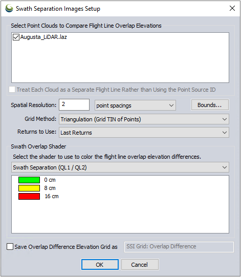
Select Point Clouds to Compare Flight Line Overlap Elevations
Select the point clouds to use in the Swath Separation analysis from the list of loaded point clouds.
Enable Treat Each Cloud as a Separate Flight Line to conduct the swath separation analysis based on the layer overlap instead of the swath ID (Point Source ID).
- If the flight lines are not separated by layers or identified in an Point Source ID attribute, the Find Flight Lines (Swaths) tool in the Lidar Analysis menu can be used to identify flight lines within point clouds.
Optionally use the Bounds button to set the bounds of the data to be considered in the analysis.
Spatial Resolution
Set the spatial resolution for the analysis in point spacings, meters, or feet. This will be the pixel size of the generated Swath Separation Image.
Grid Method
Select the grid method you would like to use. The default is Triangulation.
Triangulation uses a triangulated irregular network connecting the known elevation values.
A Binning Method lays a regular grid at the specified spatial resolution over the point cloud within the defined boundaries of the operation. The minimum / maximum / average / median of point elevations (or the value specified in Grid Type) in each bin rectangle are found. The determined minimum / maximum / average / median value of each bin or polygon is representative of the point values within it. While it will speed up an operation, Binning changes the way data is shown at small scales and can result in decreased accuracy.
Returns to Use
Select to use All Returns, Single Returns, or Last Returns in the analysis.
Swath Overlap Shader
Select the shader to use to display the swath separation. Two shaders build for this tool comply with the USGS Lidar Base Specification.
-
Swath Separation Overlap Difference (QL1 / QL2)
-
Swath Separation Overlap Difference (QL0)
Save Overlap Difference Elevation Grid as
Check this option and provide a file name to generate an elevation grid in addition to the imagery. The grid will be created using the same parameters specified for the image portion of the tool.