Geometric Segmentation
Find Geometric Segmentation in the Classification - Advanced Options section of the  Automatic Point Cloud Analysis tool.
|
|
This tool requires Global Mapper Pro |
Point Cloud Segmentation is a user guided, automatic tool that breaks the point cloud into smaller groups called segments based on the spatial and attribute relationships between points in the point cloud. By segmenting the point cloud(s) into smaller sections, each with a segment ID, users are better able to select clusters of points for manual classification or further editing.
The goal of this tool is to provide users the ability to separate objects in the point cloud apart from the neighboring points to assist with classification. Objects, in this context, can be buildings, ground, cars, road paint, transmission towers, or any other things that have distinct attributes or structure from their neighbors and thus detectable by the tool. Objects are delineated based on the attributes and thresholds set in the tool by the user.
Custom segmentation parameters can be applied to Max Likelihood and custom classification methods in the Automatic Point Cloud Analysis dialog. After a segmentation has been run, specific segmentation based attributes will be added to the point cloud allowing for additional Draw modes.
To Segment a point cloud:
-
Select the Geometric Segmentation button
 from the Classification section of the Lidar toolbar or from the Automatic Point Cloud Analysis tool.
 -
Choose the attributes that best represent the features or objects you would like to segment. These attributes should distinguish the points from their neighbors. For example, flat ground points will all typically have similar Curvature, Return Numbers, and Normal values in common with each other.
-
Set the threshold values.
-
Click Segment to segment the point cloud. This button will change to show processing progress and provide the option to Cancel.
-
*Tip: Choosing appropriate settings can be a trial and error process. Use the Specify Bounds button to select a smaller subset of points for more efficient testing speeds.
-
-
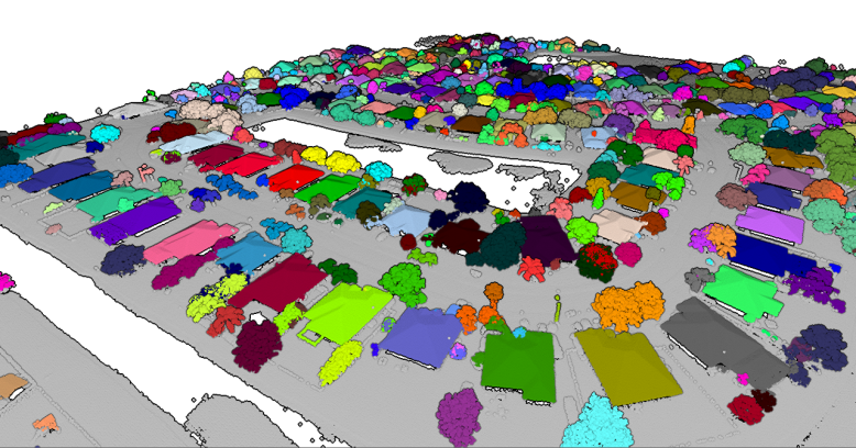
After using the Point Cloud Segmentation tool, change the Lidar Draw Mode setting to Segment ID to show the point cloud colored by segment. Colors are assigned at random.
-
Optional: Manage the generated segments by using the Segment Manger tool. Segments can be merged, deleted, etc.
-
-
Once the point cloud has been segmented, use the
 Select Lidar Segments tool from the Lidar Toolbar to select the clusters and assign a classification.
Running this tool multiple times on the same or a different point cloud during the same segmentation session (without closing the segmentation tool) will continue the counter of segment IDs so there are no repeated values.
Tiling data processing: When working with large data sets, Global Mapper will work to manage memory and machine resources. Internal tiling of the data set may be performed if the program estimates insufficient memory. If internal tiling is needed for resource management, the user will be prompted when the process is executed. After processing, the Segment ID settings can be used to merge segments.
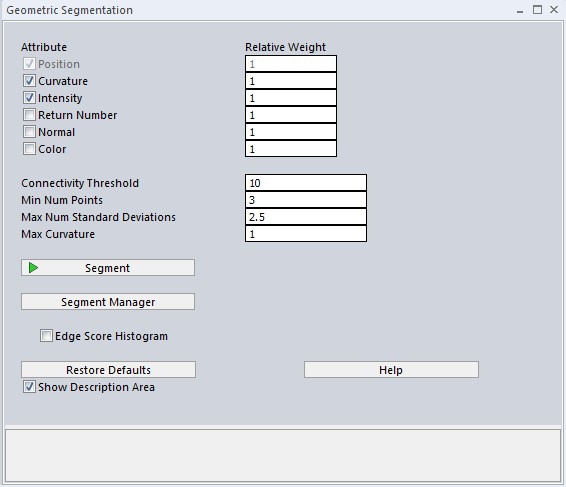
Segmentation Settings:
Attribute options are at the top of the dialog, and their thresholds are on the bottom.
Resolution
This setting is adjusted in the Automatic Point Cloud Analysis tool window.
The resolution at which to analyze the point cloud. This distance, specified in linear units or a multiple of the layer point spacing, will determine the local neighborhood size used for any given point when completing this analysis. Put simply, neighborhood size determines how far from each point the segmentation tool should look when comparing the point to its neighbors. If the neighborhood is too small, the segmentation tool might not detect the full structure of the object. Too large, and smaller structures and details may be glossed over for a less accurate result.
Attributes:
Below are the attributes that can be used to evaluate the point to point similarity that informs spectral partitioning. Select which attributes to use by checking the box next to attribute and assign a weight for the attribute. A higher value entered will result in that particular attribute being more heavily considered in the point to point similarity measure. Attributes of a point are based on statistics of a local area (neighborhood) with extent defined by the resolution.
Position refers to the X/Y/Z or Lat/Lon/Elevation position of each point return. This option is always enabled as the positional relationship between points will always be considered.
Curvature analyzes the curves created by the points in a local neighborhood. Consistency in curvature values will help indicate that points likely belong to the same object.
Intensity is the strength of the return collected. Most lidar systems record the intensity of the returning pulse. Similar materials will have similar intensity values making it useful when looking for groups of like points within a layer. Use the Lidar Draw Mode setting to visualize intensity values on a black and white gradient in the point cloud.
Return Number looks for similarity in the return number of each point return in the data set. Return numbers typically range from 1 to 5. Solid, uncovered surfaces typically have larger numbers of first and only returns while vegetation and layered objects have a larger mix of return numbers. Use the Lidar Draw Mode setting to visualize returns in the point cloud.
Normal considers the direction perpendicular to the surface the point is representing. Similar normal values over a local area indicate the points are representing a consistently shaped feature.
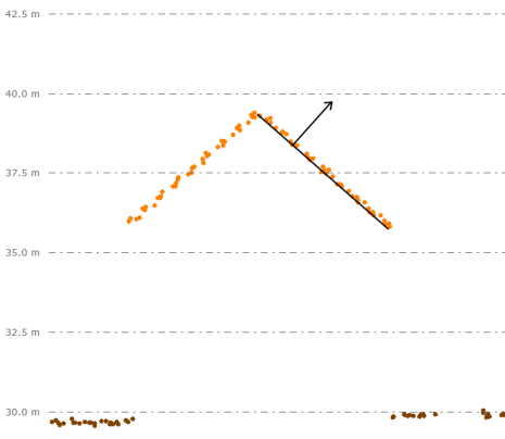
The normal of a lidar point can be depicted as a ray or arrow perpendicular to the surface the point represents. Looking at the cross section view of a roof, the plane of the roof is the surface represented by the points, and the normal for a single point is shown perpendicular to this plane moving away from the point.
Color considers the RGB color attribute associated with returns in the point cloud. In some data sets, similar colors may indicate that points represents parts of the same feature and should be included in the same segment.
Thresholds:
Connectivity Threshold is the threshold value for algebraic connectivity that is used to determine where to cut when dividing segments. A larger value will result in more segments. In general, a low value (such as a decimal below 1) would be used for large data sets where many different types of points are included. A high value (such as 50) would be used when trying to segment within a category or class, such as further segmenting the ground.
Minimum Number of Point in Segment determines the minimum number of points needed in a cluster for a segment ID to be assigned. This value should be set with the point spacing of the data set in mind. A smaller number will result in many more smaller segments, while a larger number will result in fewer, larger segments.
Maximum Number of Standard Deviations narrows the range of point associations to be considered. A larger number of standard deviations will include more weakly connected points in the same segment. A lower value will likely create fewer segments but the points in each will be more closely related.
Maximum Curvature determines the maximum allowed curvature within a neighborhood in order for a cohesive segment to be identified.
Curvature is determined by analyzing how the position of adjacent points relates to one another. The maximum curvature threshold dictates the limit of curvature in a local area for a point to be considered part of the same segment.
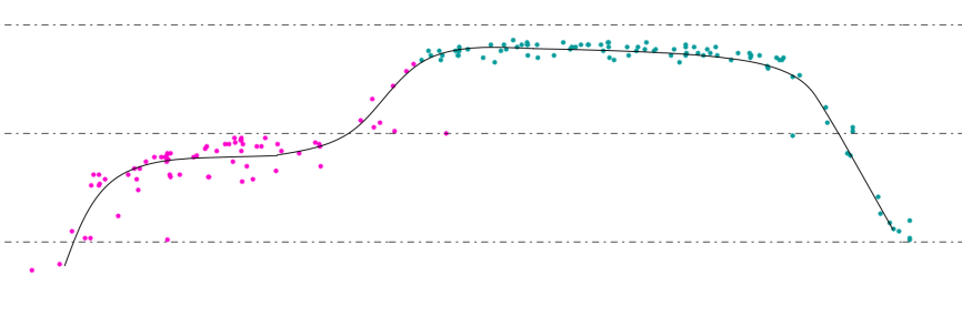
Looking at the cross profile of a car below, the point representing this one vehicle are split into two segments. The break between these segments happens at the top of the windshield area where the curve along the surface of the car is at its sharpest over a local area. If the curvature value were to be increased for this data, the car could be assigned a single segment ID.
Segment Manager
The Segment Manager button opens a dialog that allows users to select existing segments to exclude from the next Segmentation analysis, Merge segments, or Rename segments.
Particular phenomenon or objects can be excluded from a subsequent segmentation process by selecting them from the list, for example a segmentation looking to target vehicles in a parking lot might explicitly exclude some other signs or structures in the parking lot. The tool can also be used to merge segments together, for example, merging two or more segments that represent a car into one segment for the entire car. Use the Select Lidar Segments tool to select them on the map, then check the Use Only Segments Selected in Digitizer to sync with this editing tool.
Available Segments
The Available Segments section lists all currently identified segments in the point cloud layer(s). Use the check boxes to select segments to merge or exclude. Selected segments will populate the Selected Segments section of the dialog.
The option to Use Only Segments Selected in Digitizer will hide all segments in the Available Segments list and populate the Selected Segments list based on the digitizer selection.
Double click on a Segment ID value in the Available Segments list to alter the segment name.
Exclude or Merge
Exclude Selected Segments from Segmentation Process
To Exclude Selected Segments from Segmentation Process select this option and leave the Segment ID(s) Settings dialog open as you execute the segmentation analysis. The selected segments listed in the Selected Segments section will be ignored in the segmentation process and remain unedited.
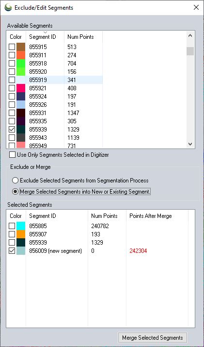
Merge Selected Segments into New or Existing Segment
To merge segments, select the segments to merge through the Available Segments section, and enable the Merge Selected Segments into New or Existing Segment option under Exclude or Merge.
When this option is enabled theSelected Segments list will show the selected segments along with a new segment ID containing zero points. In the Selected Segments section enable the check box for the segment ID you would like to keep and click Merge Selected Segments to assign all the points in the Selected Segments to the checked segment ID to keep.
Selected Segments
The Selected Segments section of the dialog lists the segments selected to either merge or exclude.