Calculate Relative Elevation Grid
The Calculate Relative Elevation Grid (from Terrain and line...) tool creates 'flattened' digital terrain models called Relative Elevation Grids, also called River Elevation Models(REM), based on the elevations along a linear feature in order to highlight the changes within the surrounding terrain, relative to the selected feature.
To use this tool, you need a raster terrain layer and a line feature. The REM layer is calculated from the difference between the original input terrain, and an intermediate raster terrain layer generated based on interpolated Inverse Distance squared Weighted (IDW) elevations pulled from the original terrain nearest to the line feature. The intermediate layer can be viewed and edited using the Settings and Advanced Settings available in the tool and described below.
Relative Elevation Grids aren't limited to rivers. They can be used to visualize any sort of line feature that moves across a terrain, including but not limited to: glacial and volcanic features, powerlines, highways, pipelines, etc.
Find the Create Relative Elevation Grids... tool in the Terrain Analysis Menu.
For Example:
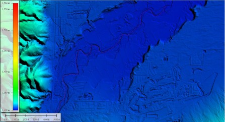
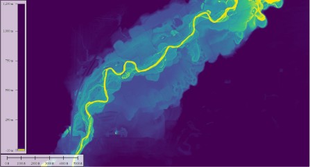
Compare a standard Digital Elevation Model (Left) to a River Elevation Model (Right) of the same area. We know that rivers flow down hill, so an REM removes that trend from the data. They are useful for measuring the change in elevation as compared to the line feature (river), instead of comparing it to sea level.
Multiple Lines
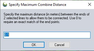
Select the line feature(s) to be used in processing before opening this tool from the Analysis drop down menu. If multiple line features are selected, Global Mapper will attempt to join the lines into one feature. The Specify Maximum Combination Distance window (pictured below) lets you determine how close together line end points need to be in order to be joined into one line feature. Any number of line features can be used. If the lines are not close enough to be joined, you can manually draw a feature to join them by using the Digitizer Tool.
General Options
The Relative Elevations Grid dialog (pictured below) allows the user to specify the output resolution. The generated REM will be displayed with the REM shader by default. Previous settings will be remembered by default when the tool is rerun, if still valid to the new application; otherwise it will repopulate with the default values when the tool is reopened.
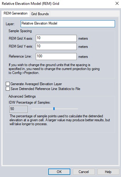
Sample Spacing
REM Grid X/Y-axis spacing - These values determine the resolution or grid cell size of the generated REM. Will be same as input terrain by default.
Reference Line spacing - The center line will be resampled at this spacing. Smaller is usually more accurate, but will result in a longer REM generation time.
Settings
Generate Averaged Elevation Layer - Enable this option to display the intermediate average grid used in calculations. The final REM grid is the difference between the original input terrain and this grid. Assessing this layer can indicate the source of any problems and needed adjustments in input parameters. Elevations are calculated using the Inverse Distance Weighted (IDW) method, where distances are from grid cell to a set of nearest center line sample points.
Save Detrended Reference Line Elevation Statistics to File - Enable this option to save a CSV file listing the calculated average elevations along the re-sampled center line and residuals. This can indicate problem areas, such as near sharp bends in river, that may require adjustments in input parameters for best results.
Advanced Settings
IDW Percentage of Samples - The percentage of sample points used to calculate the detrended elevation at a given cell. A larger value may produce better results, but will take longer to process.
Bounds
The Bounds button allows the user to set up the portion of the loaded elevation grid data they wish to consider when generating the contours.