Advanced Vector Display Configuration
The Advanced section of the Vector Display Configuration contains settings related to attributes, snapping behavior, and other options for feature display and creation.
Access the Advanced Vector Display Configuration by selecting the  Configuration button from the File Toolbar or Tools menu, and navigating to the Advanced section in the Vector Display folder.
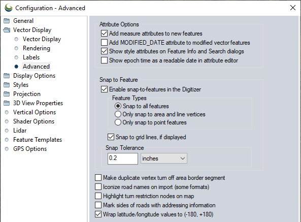
Attribute Options
Add Measure Attributes to New Features
If checked, measurement attributes like LENGTH, PERIMETER, and ENCLOSED_AREA will be autocratically added to new area and line features created with the Digitizer Tool.
Add MODIFIED_DATE to Modified Vector Features
If checked, a MODIFIED_DATE attribute is automatically added or updated for vector features when they are created or edited. The attribute value is the computer system date.
Show Style Attributes on Feature Info and Search Dialogs
If checked, the style attributes for a feature can be seen when using the Feature Info Tool or the Search tools.
Show Epoch Time as Readable Date in Attribute Editor
With this option enabled, recognized epoch time/date columns will be reformatted in the attribute editor. Automatically recognized attributes need to meet the following criteria: the attribute name contains date or time, the first 50 values are whole numbers, and the first 50 values are all above 788965200 (epoch for 1995).
Enable Snap-to-Features in the Digitizer
This option enables automatic snapping to nearby features when using the Digitizer tools. Holding the ALT key is a shortcut toggle to enable or disable snapping, while actively adding or moving vertices with the Digitizer tools.
Feature Types
Snap to All Features
When selected snapping will occur near any part of a vector feature, including along a segment for area and line features.
Only Snap to Area and Line Vertices by Default
When selected the Digitizer Tool will only snap to vertices of area and line features. Holding down the 'V' key when drawing will also toggle this behavior for a single action.
Only Snap to Point Features
When selected snapping will only occur when near point features.
Snap Tolerance
Specify how close to a "target" the cursor must be in order to activate the snap. This is measured in screen units.
Note that in previous versions of Global Mapper, snap tolerance was controlled by means of a registry entry. That registry entry is no longer valid.
Snap to Grid Lines if Displayed
This enables automatic snapping to nearby grid lines features when drawing in the Digitizer Tool.
Additional
Make Duplicate Vertex Turn Off Area Border Segment
This allows you to use duplicate area vertices to turn segments of the area border on and off. This is known as Pen Up/ Pen Down display. How it works is that the border pen is on (down) at the start of the border. Whenever a duplicate vertex is encountered, then pen is turned off for the next segment. So if for example you had vertex 1, then a duplicate vertex 2 and 3, then non-duplicate vertices 4 and 5, you would get a border drawn from vertex 1 to vertex 2, then it would turn off for 3-4, then be drawn again for 4 onto the end.
Iconize Road Names on Import (Some Formats)
If checked the specified name for road line types is tested on import to see if it can be iconized (such as for interstates and major highways). If road names can be iconized they will be. This is only done for formats which do not already have their own built-in iconization (such as Tiger /Line and USGS DLG files). This will work for formats like Shapefiles and MapInfo MIF/ MID files (among others).
Example
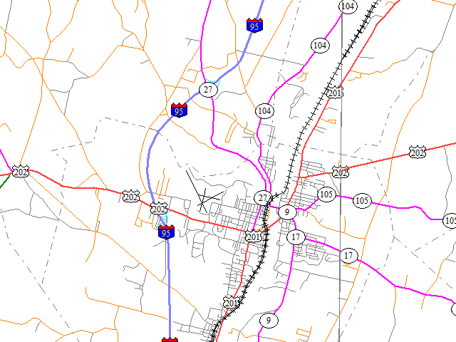
With this setting enabled, the road labels on these roads are shown with conventional shield icons.
Highlight Turn Restriction Nodes on Map
This will highlight line data with a TURN_RSTRS attribute. The value should start with 'F' or 'L' indicating whether the first or last vertex of the line should be highlighted. This is designed for creating map data for GPS devices. This will create a white circle indicator around the vertex of the line.
Mark Sides of Road with Addressing Information
This option allows you to have the sides of roads with recognized address numbering information to be marked with a series of parallel lines extending from the road on when address information is known. This provides a visual way to see where addressing information is available.
Wrap Latitude/ Longitude values to (-180, +180)
When checked, area features created close to 180° will automatically wrap to the correct coordinate values, rather than creating coordinates out of range.