 Generate Breaklines from Terrain Grid
The Generate Breaklines (from Terrain Grid) command analyzes curvature in digital terrain models to automatically extract breaklines as 3D line features. Breaklines are different from contour generation as breaklines are only created where there is a distinct change in elevation, rather than at a specified elevation interval.
This tool creates multiple lines simultaneously over a specified area or layer. To create individual lines for specific features, see Guided Breakline Extraction.
Create breaklines by choosing this option in the Terrain Analysis menu or using the  Generate Breaklines button from the Analysis Toolbar.
|
|
This tool requires Global Mapper Pro |
Quick Steps to Generate Breaklines from Terrain:
Select the Generate Breaklines tool, then choose the terrain layer to perform the edits on (if multiple are loaded).
If necessary, change the General Options settings (Layer Name, Sample Size, Smooth Breaklines) from their default options to better fit the data.
Choose 1 of the 3 Methods for Generating Breaklines:
-
Find Breaklines at Slope Region Boundaries
-
This method generates breaklines around the edges of flat areas. This is useful for tracing the edges areas such as a hydro flattened water body, shoreline, or a plateau, and is well-suited for lower-resolution terrain.
-
-
Find Breaklines Around Edges of Regions with Similar Slopes
-
This method generates breaklines around areas with consistent slope - pile edges, etc. This method is still under development.
-
-
Find Breaklines at Any Surface Break.
-
This method generates breaklines on the edges of curvature based on which Grid Type is chosen. It's useful for creating lines along ridges, valleys, ditches, etc.
-
Adjust method settings from defaults, if necessary. Default settings are based on the resolution of the data.
Click OK to run the tool. The breaklines will appear as a new line layer in the Control Center.
When selected, the command displays the Generate Breaklines dialog (pictured below) which allows the user to specify breakline thresholds and choose a processing method.
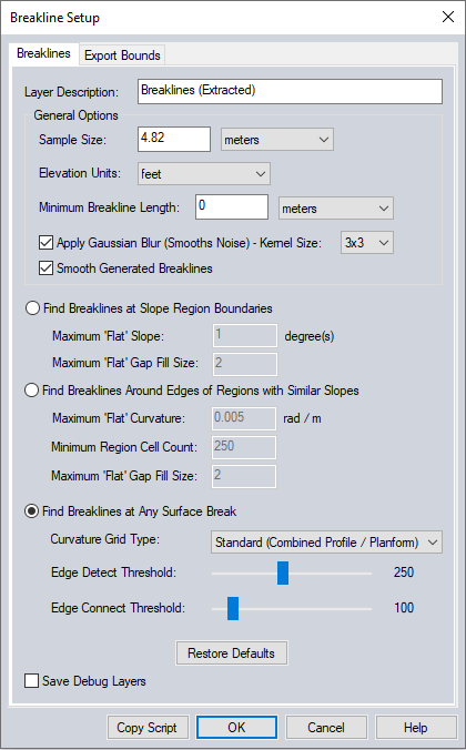
General Options
Sample Size
Before processing, the terrain grid is resampled to a grid at the resolution of the specified Sample Size. Larger sample sizes will highlight the more drastic changes in elevation and may erase the subtle changes. Sample Sizes less than 1 meter may have substantial noise.
Similar to Bin Size, the Sample Size is how far from each elevation point to look for other variation in elevation.
-
Smaller sample sizes will give results that are more relative to the local area, while larger sizes will take more of the surrounding terrain into account.
-
Larger sample sizes will look at more of the surrounding area and can weed out the smaller changes that are less drastic.
Elevation Units
Set the elevation units for the breaklines in Feet or Meters. This unit does not have to match the original file.
Minimum Breakthrough Length
The minimum breakthrough length option lets the user specify the shortest breakline that's still valid. Lines shorter than this length will be discarded. (Features discarded by this setting are marked as deleted features. To see them, turn on the Configuration option to Show Deleted Features.)
Apply Gaussian Blur (Smooths Noise)
This option allows you to apply a weighted-distance Gaussian blur to smooth noise out of the data.
Kernel Size lets you choose the neighborhood size for measuring noise levels. Larger kernels can help with noisy or very high resolution data.
Smooth Generated Breaklines
Select this option to add additional vertices along the breakline features to improve their appearance.
Find Breaklines at Slope Region Boundaries
This method generates breaklines around the edges of flat areas. This is useful for tracing the edges of areas such as a hydro flattened water body, shoreline, or a plateau, and is well-suited for lower-resolution terrain.
Maximum 'Flat' Slope - This option specifies the threshold between sloped and flat terrain. Enter the maximum gradient that terrain can have and still be considered 'Flat'. Applicable values are within 0 - 15 degrees.
Maximum 'Flat' Gap Fill Size - Set the largest horizontal distance of 'flat' terrain that a slope can be interrupted by and still be considered a continuous slope. This horizontal distance is measured as the number of grid cells, size specified by the Sample Size setting.
Find Breaklines Around Edges of Regions with Similar Slopes
This method works by generating a Standard Curvature grid, then finds closed contours in that curvature grid around regions that are 'flat' based on the flat curvature threshold. This method is still in development.
Maximum 'Flat' Curvature - This value determines the boundaries of 'flat' regions. Enter a value between 0 and 2 rad/m.
Minimum Region Cell Count - The smallest number of continuous cells that can be considered to be a region.
Maximum 'Flat' Gap Fill Size - The maximum number of non-flat cells to skip over and replace with flat values. An indirect measure of how much variation is allowed within a 'region'.
Find Breaklines at Any Surface Break
This method generates breaklines on the edges of curvature based on which Grid Type is chosen. It's useful for creating lines along ridges, valleys, ditches, etc, and works well with Lidar.
Options for this method allow the user to choose which Curvature Grid is created for the edges to be found and extracted from. Curvature is a parameter that describes the bending degree of the terrain surface.
The generated grids are not included in the extracted breaklines layer. To create a curvature grid, use the Create Curvature Grid tool in the Terrain Analysis drop down menu.
Curvature Grid Type: Select a grid type that matches the type of terrain change to be extracted.
-
Profile - Curvature in the Z axis parallel to the slope direction.
-
Planform - Curvature perpendicular to the direction of the maximum slope.
-
Standard (Combined Profile and Planform) - Combines the profile and plan curvature into a single value.
-
Slope - This option creates a slope grid instead of a curvature grid. When generating breaklines, it will use the parameters specified for the Find Breaklines at Slope Region Boundaries method in addition to the parameters in this section.
Edge Thresholds:
These threshold values are used in edge detection to find the breaklines in a grayscale image generated from the curvature or slope grids. The units are indirectly related to grayscale values.
The Edge Detect Threshold must be at least as large, or larger than the Edge Connect Threshold.
Edge Detect Threshold - Edges with an intensity gradient above this threshold are considered to be breaklines. A lower threshold value will result in more breaklines identified.
Edge Connect Threshold - The Edge Connect Threshold influences how breaks in the line are handled in situations where there may be inconstancy in the edge being detected. Choose a lower value to generate longer, more connected breaklines.
Export Bounds
The Export Bounds panel allows
the user to set up the portion of the loaded elevation grid data they
wish to consider when generating the contours.