Terrain Painting
Terrain Painting is a set of terrain editing tools that provide the ability to interactively modify the elevation values of a gridded elevation dataset. The Terrain Painting toolset includes operations like filling gaps in the terrain with interpolation, raising or lowering the existing elevation inside of a defined area, or setting a specific elevation height. Dynamically editing a terrain dataset unlocks new possibilities in site planning, modeling, and cleaning up or improving sensor derived elevation data. This tool works with all types of gridded elevation datasets, including DSMs and DTMs, bathymetric datasets, lidar derived terrain data, and more.
To begin terrain painting, select the  Terrain Painting button from the Analysis toolbar or the Terrain Analysis menu.
|
|
This tool requires Global Mapper Pro |
Select the Terrain Painting tool, then choose the terrain layer to perform the edits on (if multiple are loaded).
Choose the operation type, then the brush type. Adjust brush size and other parameters to match the desired effect. The cursor will indicate brush size (red) and feathering (blue) that has been set.
Click on the map to perform the edit. When using the line or area brush type, left-click to define vertices, then right-click to complete the shape and apply the edit within that area.
The undo and redo operations can be used throughout the session, including when the tool is closed and reopened. If the workspace has been closed and reopened, it will not be possible to undo edits from the previous session, but the revert to original heights brush will still work.
To move around the dataset while the terrain painting tool is active, click and drag the middle mouse wheel, or use the pan arrow icons at the edge of the map.
Note: Modifications to the terrain are stored in the workspace. The original file is not directly edited. To create an updated terrain dataset (as a stand alone file), export the data to a new file.
Note: To use terrain painting operations on terrain data loaded from an online dataset, first export the data to a local file and then make edits to the copy.
The Terrain Paint options is a floating dialog that will appear while the terrain painting tool is active. This dialog controls the shape and size of the edits applied, as well as what operation is performed in the selected area.
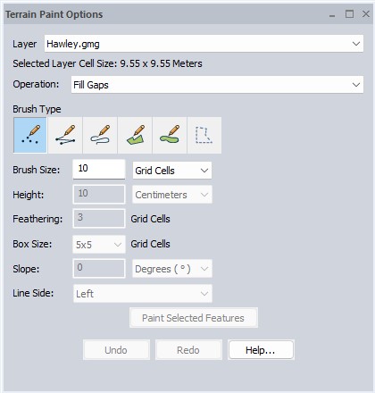
Layer
If multiple terrain datasets are loaded, select which terrain layer to perform the modifications on. Only one terrain layer may be edited at a time.
Selected Layer Cell Size will show the resolution or grid cell size for the terrain layer currently being edited. This information can also be found in the layer's Metadata.
Operation:
Fill Gaps - This brush calculates inverse distance weighting (IDW) from nearby pixels to fill in areas that have no elevations. This only applies to the pixels that have a 'no data' value set, and like other operations, will only create data within the bounds or the original terrain dataset.
Smooth Terrain - Average - The smoothing operation will perform a focal average for all of the cells inside the brush area, based on the specified box size. The default will look in a 5X5 neighborhood around each pixel in the brush area, and update that pixel to be the average value of all the pixels in the neighborhood box. This is similar to the box average resampling method that can be applied to the whole layer, but in this case it is only applied within the specified brush area.
Raise Terrain Height- This will incrementally increase the height of the terrain in the specified area. The height value sets the amount the terrain is raised. .
Lower Terrain Height-Incrementally decrease the height of the terrain in the specified area. The height value controls the amount the terrain is lowered.
Set Terrain Height - Changes the terrain height to match the Height value specified in the dialog.
Slope Terrain Along Line - This operation changes the elevation to match the specified slope along the drawn line. The starting height is derived from the first vertex of the line. The terrain will slope up (positive slope) or down (negative slope) from the first vertex toward the end of the line, matching the specified slope value. For example to create a highway ramp, start the line at the existing highway surface and enter a negative slope, drawing the line along the center-line of the new ramp location to slope the terrain down at the specified grade.
Slope Terrain Across Line - This operation changes the elevation to match the specified slope perpendicularly from the drawn line. The slope is drawn from the middle of the line out to the left, right, or both sides as determined by settings. See the Examples at the bottom of this page.
Set as "No Data"- This setting will erase the specified part of the terrain and set it to a null 'No Data' value.
Revert to Original Heights- This tool will selectively erase edits that have been made to the terrain dataset to revert the specified area back to original values.
Brush Type:
The area that will be edited can be defined by clicking at a point, drawing a line, or drawing an area. The brush type toggles between these different options for selecting the area of the terrain to be edited.
 Point - The point brush will apply the specified operation at the clicked location. Note it is necessary to click at each location to apply the edit; click and drag is not implemented.
 Line - This brush will apply the operation along a line, with the width based on the brush size and other settings. Left-click to place the first vertex and additional vertices, then right-click to complete the line and apply the edit. Use the undo button to remove the last vertex placement.
 Line (Trace Mode) - This brush will automatically trace the operation as the brush moves, applying the changes to the terrain layer when the mouse is released. The line width is based on the brush size and other settings. Hold the left mouse button as you move the cursor across the terrain to draw the operation, then release the mouse to apply it.
 Area- Apply the edit operation within a defined area. Left-click on the map to place each of the vertices, then right-click at the last vertex to close the area and apply the edit.
 Area (Trace Mode) - This brush can freehand trace an area feature without having to create multiple vertices, similar to a lasso tool. Hold the left mouse button while moving the cursor to draw a line, then release the mouse to automatically close the line into an area feature and apply the operation to the area.
 Selected Features - This option allows for a chosen operation to be applied one or more selected vector features simultaneously. Once the features have been selected with the Digitizer tool the Paint Selected Features button will enable. Click this button to apply the chosen operation to the selected features.
Other Options:
Based on the resampling method set for the terrain layer, it is not always clear how coarse the terrain data is. For terrain data the default resampling method is bilinear interpolation, which will smooth the display of the data rather than show the coarse raw pixels. To see the raw pixel values without interpolation, set the resampling method to No Resampling (Nearest Neighbor).
Brush Size - Specify the brush size. Units can be changed to Feet, Meters, or number of Grid Cells. The size of the Grid Cells, also called pixels, is explicitly tied to the resolution of the original dataset. To see the resolution of the terrain data, look at Grid Cell Size at the top of the dialog, or go to the metadata.
Height - The height value is used to set the terrain height or increase /decrease interval.
Feathering - The feathering effect will taper off the edges of the operation. This effect works in combination with the tools to set terrain height and raise and lower terrain. The brush will gradually change the pixels beyond the red circle range to match the values just outside of the feathering zone, shown by the blue circle. This is similar to Feathering Tab options, but occurs only in the local area where the edit was made.
Box Size - For the smoothing operation, the box size controls how large of a neighborhood of cells to compare to calculate the new smoothed pixel.
Slope - The slope value sets the slope for Slope Terrain Along Line and Slope Terrain Across Line operations. The slope begins at the starting vertex for slope terrain along line. Use positive values to slope up, and negative values to slope down. For the slope across line operation, the slope is applied moving away from the line (left, right or both sides), based on the elevation where the line is drawn. Slope ratio is rise over run.
Line side - Left, Right, or Both sides are from the perspective of the beginning of the line. The Line Side option is only used in the Slope Terrain Across Line operation.
Examples
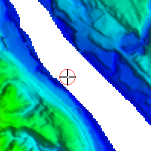
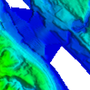
The fill gaps operation was used to fill in a missing part of the terrain where the river bed is in the below images.
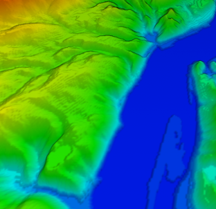
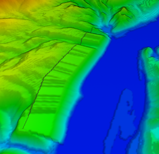
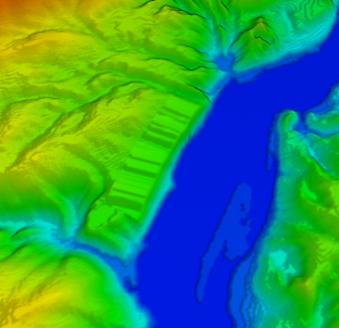
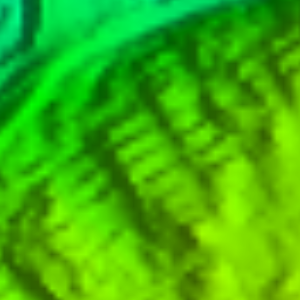
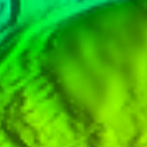
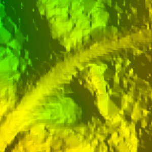
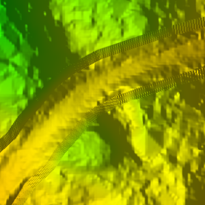
The smooth operation was used in this area to smooth out some terracing in the landscape in the below images.
The Raise Terrain height tool was used to elevate this road feature. The feathering effect created a sloped edge away from the elevated road back to the surrounding terrain.
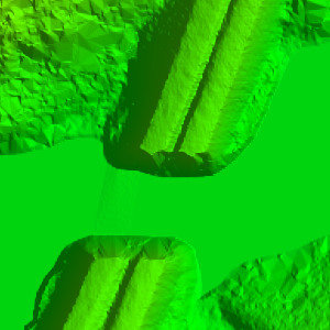
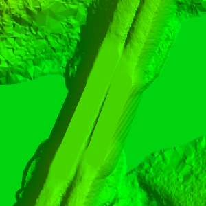
The Set Terrain Height was used to reconnect this bridge.
The Slope Terrain Across Line was used to create a more even slope along a river bank. The slope was drawn to the right of the gray line.