Loading Microsoft Excel Files
When a Microsoft Excel file (*.xls, *.xslx) is opened the Excel File Import Options dialog allows the options for import to be specified. Excel files must contain coordinate values next to each other in the file to import properly, but they can be in either order and do not need to be the first value in the row. This order, as well as other special file formatting, can be specified using the various settings on the import dialog.
If the Excel sheet does not contain coordinate values, see Joining a Table.
The Excel File Import Options dialog has several options that allow you to define how your data is formatted.
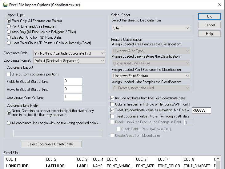
Prior to loading a Microsoft Excel file, it is necessary to know which column contains the coordinates, and which coordinate comes first. Also note whether there is a header or label row at the beginning of the file, and if there are Z-values included in the geometry.
- Select the type of geometry to import in the Import Type section.
- Specify which coordinate comes first in the Coordinate Order.
- If the coordinate is not the first value/column in the file, specify Fields to Skip at Start of Line to get to the coordinate value.
If the file has header rows at the top (other than column labels) before the values begin, specify Rows to Skip at Start of File. - In most cases the Coordinate Delimiter can be left at Auto-Detect, unless there are text fields that contain punctuation and special characters within the values, such as address fields.
- Use the check boxes at the bottom right to specify whether to import additional values as attributes, whether the first row contains attribute names, and whether to use the 3rd coordinate as an elevation value.
- Optionally specify a Feature Type to assign to the loaded vector features.
- Some files may require the use of additional settings on the dialog, as described below.
Select Sheet
This drop down allows the selection of the specific sheet from which data should be loaded. If multiple sheets contain data that should be loaded, multiple imports will be needed.
Import Type
The Import Type section allows the user to specify how they want the data in the file to be treated. The different import types are defined as follows:
- Point Only - All lines from the file which are determined to contain coordinate data will result in a single point feature to be generated.
- Point, Line, and Area Features - Any string of two or more consecutive lines with coordinate data will result in a line or area feature. All isolated coordinate lines will result in a point feature.
- Area only - All coordinates will be interpreted as part of polygon or TIN features.
- Elevation Grid - All lines from the file which are determined to contain 3D coordinate data will be used to generate a triangulated terrain. The triangulation is gridded to create an elevation grid. This grid has all the capabilities of an imported DEM, including contour generation, line of sight and view shed analysis, and raster draping. When selecting this option, the Create Elevation Grid dialog will appear after setting up the file import options to allow setting up the gridding process.
- Lidar Point Cloud - The 3D points in the file will be loaded as a point cloud that can be rendered by elevation, intensity (if present), or classifications. You can load a XYZ file like this to use much less memory and render it much faster than loading as full point features. If you have a XYZI (XYZ + intensity) the intensity is also applied to the point cloud.
Coordinate Format and Layout
The Coordinate Order value allows the user to specify in what order
the coordinates are found on coordinate lines in the file. Coordinates
can either be x followed by y (i.e. longitude then latitude) or the reverse.
Global Mapper supports coordinates in decimal format as well as degree/minute
and degree/minute/second coordinates. Elevation values, if present,
are always assumed to come after the x and y values.
The Coordinate Format option allows the user to specify how coordinate values are stored. The default option supports several formats, including using the exact decimal representation for the coordinate and automatic recognition of separated latitude/longitude degree values, such as DD MM SS with a large variety of supported separating characters. Support also exists for packed decimal degree values in the formats DDMMSS.S and DDMM.M.
Global Mapper also supports coordinates listed in Earth-Centered Earth Fixed XYZ coordinates. Set the Coordinate Format to ECEF to load data in this format.
Files with WKT (well-known-text) coordinate strings, allowing line, polygon, and point feature coordinates all on a single line can also be loaded. In, MGRS (military grid reference system) and UTM-K (Korean) coordinate strings are also recognized formats.
The Use Custom Coordinate Positions option allows the user to specify which columns contain the X and Y data. Note that the first column is 0, the next is 1, etc. This is used when the coordinate columns aren't adjacent to each other, or are to the right of fields that can't be skipped.
For Example: If the x coordinates
are in the 2nd column and the y coordinates are in the 4th column, set the X/Y Column Index to 1 and 3. The specified columns will be bolded in the File Preview window.
The Fields to Skip at Start of Line setting controls what field index (column) the coordinates start in. For Example: If the x and y coordinates are in the 3rd and 4th columns, setting this value to 2 will ensure that the coordinates will be grabbed from the appropriate place.
The Rows to Skip at Start of File setting controls how many lines to skip at the start of the file before trying to extract data. This is useful if some header lines at the start of the file should be skipped over.
The Coordinate Pair Per Line setting controls how many pairs of coordinates are read per line. How the coordinates are connected is impacted by the import type setting.
Special Coordinate Formatting
The Coordinate Line Prefix section allows the user to specify whether coordinates start at the beginning of the line or if coordinate lines start with some other sequence of characters. For example, some formats may start coordinate lines with the sequence "XY,".
Pressing the Select Coordinate Offset/Scale button displays a dialog that allows the user to select an offset and scale factor to apply to each coordinate. The offset entered will first be added to each coordinate, and then each coordinate will be multiplied by the scale factor.
Feature Classification
The Feature Classification section allows the user to specify what feature type to assign to area, line, and point features imported from the file or the Lidar classification to assign to Lidar features.
If the Include attributes from lines with coordinate data option is selected, any text found after the coordinate values on the line will be included as attributes for that feature.
Settings for Additional Values
If a Point Only import is being performed and the Column Headers in First Row of File option is checked, values in the first line from the file will be used as the attributes names for the attributes found in coordinate data lines.
If the Treat 3rd coordinate value as elevation option is selected and a numeric value is found immediately following the x and y (or lat and lon) coordinate values, that value will be treated as an elevation. Otherwise, the value will be included as an attribute if the Include attributes from lines with coordinate data option is selected. Typically, this option should remain checked unless point data is being imported in which the 3rd column is an attribute that occasionally contains all numeric values (i.e. well names).
If line and/or area data do not have non-coordinate lines separating them, but are delimited by a change in a particular field of data, use the Break Line/Area Features on Change in Field option to specify which field (use a 1-based index) indicate a separation of line and/or area data. This will breaking the data into separate line/area features. If the break field consists of 1 and 0 values, where 1 is the start of a new line/area feature, the Break Field is Pen Up/Down (0/1) option can be used.
Special Attributes
When generic ASCII text files are imported, Global Mapper will scan the attributes associated with each feature and look for any attribute names that are known to it. The following is an abbreviated list of attribute names that are currently recognized by Global Mapper when generic ASCII text files are read:
-
NAME or LABEL - The value associated with an attribute of either of these names will be used as the feature name.
-
DESC, DESCRIPTION, LAYER, or TYPE - The value associated with an attribute of any of these names will be used as the feature description.
-
GM_TYPE - The value associated with an attribute with this name or any of the description names listed above will be used to attempt to assign a classification other than the default for each feature. The value must match one of the classification names in Global Mapper to work. It will also work for user-created custom types.
-
ELEVATION, HEIGHT, or DEPTH - The value associated with an attribute of any of these names will be used as the feature's elevation.
-
SYMBOL, POINT SYMBOL, or POINT_SYMBOL - The values associated with an attribute of any of these names will be compared against the names of the symbols available in Global Mapper (including any custom symbols). If a match is found, that symbol will be used for the point feature. These attribute names are ignored for line features. The user can also specify custom dot and square symbol colors and sizes without having to add custom bitmaps for those symbols. Use names of the form DOT_CUSTOM_[SIZE]_[RED]_[GREEN]_[BLUE] and SQUARE_CUSTOM_[SIZE]_[RED]_[GREEN]_[BLUE] where the [SIZE] value is the radius in pixels of the dot or square, and the [RED], [GREEN], and [BLUE] values represent the color to use. For example, to specify a dot symbol of radius 10 pixels with a color or green, would be a symbol name of DOT_CUSTOM_10_0_255_0.
-
COLOR - The COLOR attribute should be formatted as RGB (red,green,blue), in the absence of a specific fill or line color, this will be used.
-
LINE COLOR, LINE_COLOR, BORDER COLOR, BORDER_COLOR, PEN COLOR, or PEN_COLOR - The values associated with an attribute of any of these names will be used as the color for the pen used to draw line features. These values must be formatted according to the guidelines for the COLOR attribute in order to be recognized.
-
LINE WIDTH, LINE_WIDTH, BORDER WIDTH, BORDER_WIDTH, PEN WIDTH, or PEN_WIDTH - The values associated with an attribute of any of these names will be used as the width for the pen used to draw line features.
-
LINE STYLE, LINE_STYLE, BORDER STYLE, BORDER_STYLE, PEN STYLE, or PEN_STYLE - The values associated with an attribute of any of these names will be used as the style for the pen used to draw line features. Valid values are Solid, Dash, Dot, Dash - Dot, Dash - Dot - Dot, and Null.
-
LABEL_ON_LINE - If this is set to "YES" or "TRUE", the label (if any) for this line feature should be rendered centered on the line.
-
CLOSED - If this is set to "YES" or "TRUE", the feature will be treated as a closed area feature if it has at least three vertices.
-
ISLAND - If this is set to "YES" or "TRUE", the feature will be treated as an island of the previous closed parent area feature if it has at least three vertices. If there are no previous parent areas, this attribute will be ignored.
-
FONT_NAME - This specifies the name (e.g. Arial, Times New Roman, etc.) of the font to use when displaying the display label, if any, for this feature.
-
FONT_COLOR - This specifies the color of the font to use when displaying the display label, if any, for this feature. The values must be formatted according to the guidelines for the COLOR attribute in order to be recognized.
-
FONT_ANGLE - This specifies the angle in degrees of the font to use when displaying the display label, if any, for this point feature.
-
FONT_SIZE - This specifies the point size of the font to use when displaying the display label, if any, for this feature.
-
FONT_HEIGHT_METERS - This specifies the height in meters of the font to use when displaying the display label, if any, for this feature. Using this causes the actual point size of the font to vary as you zoom in and out.
-
FONT_CHARSET - This specifies the numeric character set of the font to use when displaying the display label, if any, for this feature. These correspond to the Windows character set enumeration.