 Defining or Editing
a Fly-through Path
Defining or Editing
a Fly-through Path
Each vertex in a fly through path acts as a key-frame in a fly through video. When rendering the fly-through, frames will be created between each key frame to provide a smooth transition between key frames at a specified frame rate.
Each vertex in a fly-through path contains a time-stamp and elevation, and additional attributes including velocity, heading, pitch and bank angle, that are used to generate the fly-through video. These values can be auto-generated using the Fly-Through Path dialog options, or may be recognized from some vector file format data.
The Fly-Through Path Properties can be accessed from the button on the Analysis toolbar or the 3D view toolbar. It can also be accessed from the Digitizer menu or context menu under Vertex Editing >
Create 3D Fly-through, or from the Fly-Through.... button at the bottom of the Feature information or Modify Feature Info windows.
The first step is to create or choose a line feature to represent the path the camera will take. An existing
line features may be used to define the flight path. These lines can be
real-world flight path data, such as from GPS, or a line drawn using
the digitizer tool. If drawing a line with the digitizer, add a vertex at each desired key
frame location. These are points that the fly-through will hit, and act as the anchor points for settings like camera angle and velocity. ![]() Related Topics
Related Topics
To define a fly-through path, select a line feature with the digitizer tool and press the fly-through path button.
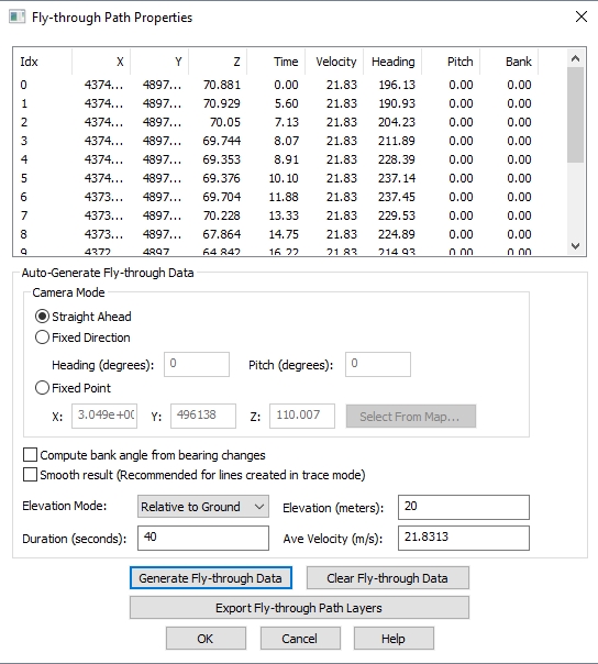
In the auto-generate fly-through data section, specify the Camera Mode (Straight Ahead, Fixed Direction, or Fixed Point).
Specify the Elevation, and the Elevation Mode for the camera.
Specify either a video Duration or an Average Velocity.
Press the Generate Fly-through Data button and see the Z, Time, Velocity, Heading, Pitch and Bank values update in the table for each vertex.
Optionally adjust the settings and press the Generate Fly-though Data button again to update. Or double click on a row and modify the values for a particular vertex.
The fly-through path is now ready for Preview, Play or Save to a video. Open the 3D view to access these tools.
The editor will show a list of line vertices. These will be the location
of key frames![]() In fly- through videos the line vertices of the fly-through path are linked to video frames that are generated based on the location and camera values for the vertex.
The video of the 3D geospatial data is calculated using the key frame values, and then smooth interpolation to calculate other video frames that transition between the keyframes.. The fly-through view requires elevation, if not already
defined in line feature, frame time, and camera heading and pitch. This
data can be auto-generated. Once generated, individual key frames can
be edited. For any point features or line vertices with recognized timestamp
attributes, a 'Time' column will be generated.
In fly- through videos the line vertices of the fly-through path are linked to video frames that are generated based on the location and camera values for the vertex.
The video of the 3D geospatial data is calculated using the key frame values, and then smooth interpolation to calculate other video frames that transition between the keyframes.. The fly-through view requires elevation, if not already
defined in line feature, frame time, and camera heading and pitch. This
data can be auto-generated. Once generated, individual key frames can
be edited. For any point features or line vertices with recognized timestamp
attributes, a 'Time' column will be generated.
Fly-through Values
- X, Y, Z— Coordinates and elevation for the key frame. Z values may already exist for the line feature, or can be auto generated from terrain data using the Elevation Mode settings.
- Time — Time in seconds at which the key frame will occur in the video. This may be auto calculated based on the video duration and distance along the line.
- Velocity — Speed, in meters per second, at which the video progresses through the terrain. This may represent actual aircraft velocity, or can be automatically calculated based on a chosen video duration . Key frame velocity may be edited to speed up or slow down through parts of the terrain. When velocity of key frames is modified, the overall length of the video and subsequent key frame times will be changed to compensate. The velocity at a vertex must be greater than 0 m/s
- Heading —Direction that the camera is pointing in Degrees relative to True North. Values may range from 0° to 360°, measured in the clockwise direction.
- Pitch— The tilt of the camera up toward the sky or down to the ground.
- Bank — Bank angle values will change the side to side tilt of the camera. The acceptable values are -180 to +180, with positive values measured in the counter clockwise direction, i.e. a positive angle rotates the camera with a dip in the left wing.
Camera Mode
To generate view data, first select the Camera Mode:
- Straight Ahead —The
camera will always point along the flight path.
- Fixed Direction— The
camera will always point at the given heading (degrees from north, positive
eastward) and pitch
(degrees from the horizontal, positive up). - Fixed Point — The camera will always point at the given point in space. The point is listed in coordinates based on the display Projection. Choose the Select from Map button to calculate vertices from a clicked map location.
Compute bank angle from bearing changes
Checking this option will auto calculate the bank angle based on the flight path. The bank angle is calculated from the turn radius and velocity, up to +/-30 degrees.
There will be a warning generated if the bank angles have been clamped to the maximum (+/-30°).
Smooth Results
Check this option to smooth the results for Camera Heading and Bank Angles. Rather than strictly adhering to the calculated values, smoothing can reduce the jerkiness of resulting image. This setting is recommended for lines that have been created using the digitizer trace tool, or are otherwise jagged.
Elevation Mode
Next select the Elevation
Mode:
- Absolute — The camera elevation at each key frame will be the specified elevation value.
- Relative to Ground
— The camera elevation at each key frame will be the specified elevation
value above the ground level at that point. When using this mode make sure
there are
key frames at each peak along the path. - Use Existing — Use the elevations already defined for the line feature.
- Elevation — height value to be calculated based on the Elevation Mode.
Duration
When rendered, the camera will move at a constant velocity such that the time to travel from first to last key-frame will take this number of seconds. Preview and Save options can be found among the Fly-through tools below.
Ave Velocity
Average Velocity is automatically calculated when a video / flight duration value is entered. Auto generated fly through data is calculated at a constant velocity, using the speed and distance along the flight path to calculate the time for each key-frame. See velocity for information about varying the velocity throughout the video.
Generate Fly-though Data
Based on the specified settings above the attributes for Time, Heading and Pitch will fill in for each frame along the line.
Clear Fly-through Data
Clear the attributes for Z, Time, Velocity, Heading, Pitch and Bank Angle.
Export Fly-Through Path Layers
Select this option for save the path to a supported format. Fly-through data can only be preserved in vector formats that support per vertex attributes. They will also be saved in a workspace file.
Exported Layers
Select the layers to include in the export in the Exported Layers dialog. Choose from the following options:
- All Active Layers - this will include all visible vector data in the export, just like an export command from the File Menu.
Be careful choosing this option with lidar data or other large data-sets loaded.
- All Active Layers with Fly-Through Paths - Export all vector data in layers that contain Fly-Through paths.
- Selected Fly-through Path Layer- Export of data in the layer of the currently selected fly-through path.
Export Format
Select the Export Format from the following options:
- Global Mapper Mobile
- Global Mapper Package
- GPX (GPS eXchange Format)
- KML/KMZ (Vector Only)
- Simple ASCII (XYZ) Text File
- Text File
- Text Files