Feature Extraction
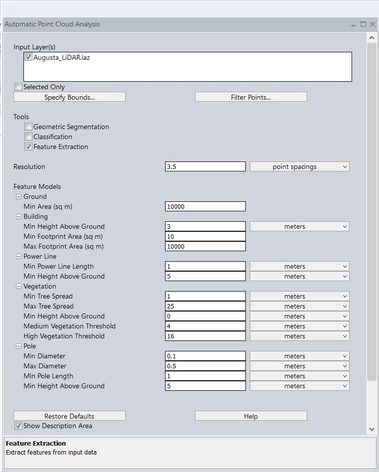
The Feature Extraction tool can be found within the Automatic Point Cloud Analysis tool
|
|
This tool requires Global Mapper Pro |
Global Mapper can automate the process of locating features on the ground by using classified point cloud data with the automated feature extraction tools available with Global Mapper Pro. The Extract Vector Features tool can be used on classified points in an entire point cloud or a user-defined subsection. This feature extraction tool lets the user derive vector features such as building footprints, building roof structures, power lines, and other structures from classified point clouds. The default parameter values can be changed by the user for improved results.
Feature extraction must be performed on a previously classified point cloud. If the point cloud contains non-standard ASPRS classes, first see Lidar Class Properties to set the proper Class Groups.
-
In the Feature Extraction Settings dialog, select which features to extract: Buildings, Powerlines, Trees, or Poles.
-
Specify the appropriate settings under each extraction type using the guidelines below. Check settings in both the Feature extraction window and the shared settings in the main Point Cloud Analysis window.
-
Press Ok to perform the extraction. See also 3D Point Symbols for visualization options for the extracted point features.
Shared Settings
Each feature type has shared settings in the main (left) window of the Automatic Point Cloud Analysis tool. These values are used during both classification and feature extraction. To see definitions of these values, check each feature's classification page.
Building Footprint Extraction Settings
*Be sure to check the additional Shared Settings from the main Point Cloud Analysis tool.
Check Extract Buildings to create 3D building vectors or mesh features based on points in the Structure/ Building Point group.
Create Approximate Ground Coverage Polygons (building footprints) - Select this option to create polygons at the base of the buildings representing the footprint.
Regularize Footprints - Check this option to regularize building footprints so that corners become 90 degrees and opposite walls are parallel. This option can only be enabled when simplify is disabled. Footprints will be regularized based on the horizontal threshold. The horizontal threshold defines the maximum distance a point can be moved to make line segments parallel or perpendicular.
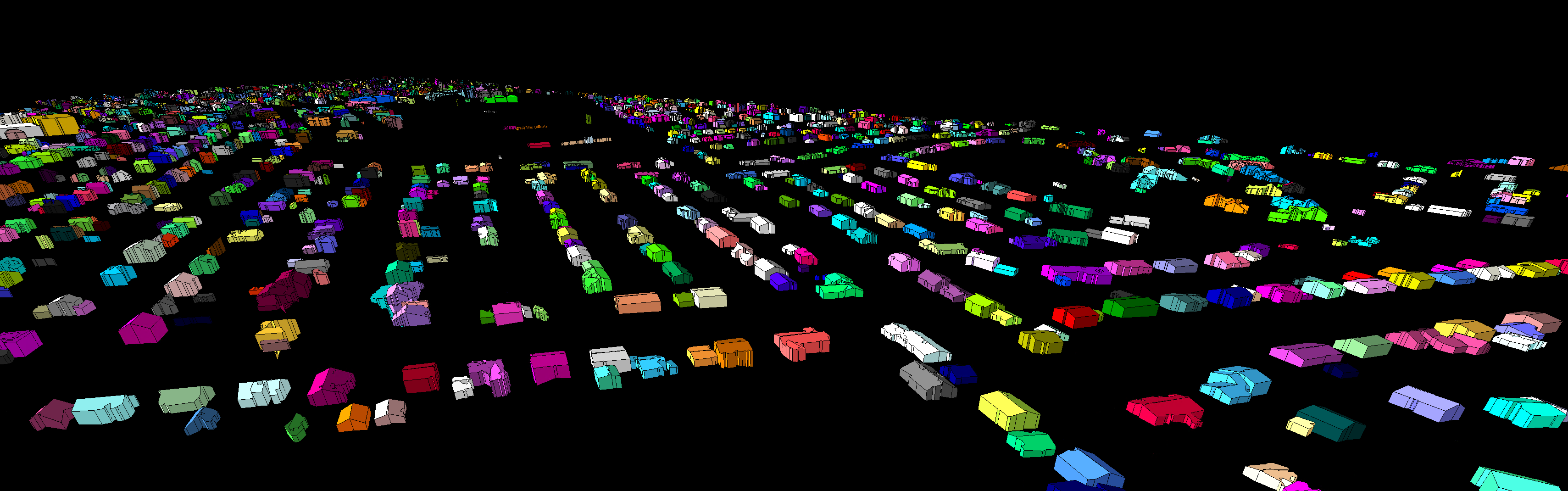
Buildings extracted using the regularize setting with roof planes and sidewalls enabled
Simplify Footprints - Check this option to simplify buildings. Extra vertices will be removed, given that they do not move the original boundary further than the specified horizontal threshold.
Minimum Footprint Area - Specify the minimum size of a building footprint in square meters. Generated footprints smaller than the entered value will be discarded.
Pin Footprints to Height - Use this option to set the elevation for all generated building footprints features to a single value.
Roof Planes - Select this option to identify and create roof features for extracted buildings.
Side Walls - Select this to generate side wall features for the extracted buildings.
Sharpen edges and stitch planes by adding points at planar intersections - This option will generate point features along intersections between planes. The points will be placed between pairs of nearby points that are contained in different planes.
Generate Mesh - If selected, the building roofs will each be turned into a single 3D mesh feature.
Color by Intensity - Use this option to color the mesh vertices by the intensity value at that location, derived from the point cloud.
Reconstruct Surface _ Reconstruction Rate - check this option and enter a value to use only a certain percentage of the building points to generate the mesh. This will create less complicated mesh features. The density of vertices will be the specified percentage of the original mesh vertex density.
RANSAC Plane Extraction Settings - This process checks different combinations of points against plane models being extracted in order to determine the best fit.
Maximum Distance to Plane - Set the maximum distance in meters from an identified plane at which a point can still be considered part of the plane.
Minimum Number of Points in Plane - Use this field to set the minimum number of points needed in an area to identify a plane and create an extracted building feature.
Max Iterations - Use this field to limit how many plane models will be tested in the analysis.
Normal Weight - This parameter determines how important the point normal vectors are in matching the points against a plane model. The point normal is the direction perpendicular to the surface the point represents.
Powerline Extraction Settings
*Be sure to check the additional Shared Settings from the main Point Cloud Analysis tool.
This option creates 3D line features from points classified as 'Wire - Conductor' lidar class 14.
Maximum Distance to Best Fit Line – Define the maximum allowable distance in meters away from the calculated best fit line for the classified powerline points.
Maximum Angle Delta Allowed – Maximum angle between points to define a co-linear powerline feature. It's the angle difference between line segments in neighboring grid cells.
Minimum Powerline Length to Keep – Defines the shortest allowable powerline segment.
Tree Extraction Settings
*Be sure to check the additional Shared Settings from the main Point Cloud Analysis tool.
This option extracts trees from point clouds containing Vegetation points. Extracted trees are represented as Vector point features, created at each individual treetop. These extracted tree points will contain measurement attributes such as: 3D Surface Area, Volume, Vertical Extent, and Spread, all which measure characteristics of the tree crown, the Elevation as measured at the base of the tree, along with the Height of the tallest tree point in the canopy.
Create Approximate Tree Coverage Polygons - extracts 2D tree features outlining the tree canopy and shape. These will contain the same attributes as the extracted tree points.
Simplify Footprints - Check this option to simplify buildings. Extra vertices will be removed given that they do not move the original boundary further than the specified horizontal threshold.
Generate Mesh - Creates 3D mesh features of the extracted tree canopies.
Reclassify by Height - Extracted trees can be assigned one of 3 lidar classifications: Low, Medium, or High Vegetation. Use the Medium and High options to set the minimum thresholds. Trees taller than these set values will be assigned the corresponding classification. All trees shorter than the Medium threshold will be assigned "Low Vegetation".
Pole Extraction Settings
*Be sure to check the additional Shared Settings from the main Point Cloud Analysis tool.
This option extracts poles from points classified as 'Transmission Tower' lidar class 15. By default the point feature is placed at the bottom of the pole. Use the option below to place it at the top instead.
Minimum Number of Points – Specify the minimum count of points that must be contained in a cluster of points to create an extracted pole point.
Mark Top of Pole – Check this option to create a point at the top of the pole. When unchecked, the point will be created at the bottom of the pole.
Restore Defaults
Restores the default settings for the Feature Extraction tool.