Bridge Generation Options
Use the Bridge Generation Options dialog to define parameters for
bridge feature creation. This
tool will create bridge features based on user defined parameters. Bridging
features (roads, etc) and Bridged features (rivers, etc) can be automatically
selected by overlay, feature type, and attributes. Features may also be
manually selected.
The following dialog will be displayed when the Bridge Generation toolbar
button  is clicked:
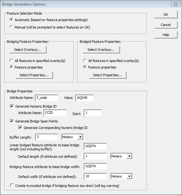
Each generated bridge will consist of a linear feature and optional span
point features. The span points will be located where the linear bridge
feature intersects the bridged feature (one point for linear bridged features,
and two for areas). A section of the bridging features will be cut out
to accommodate the bridge, and a copy of the cut section will be placed
in a separate overlay. This will allow the user to reconstruct the original
bridging feature if necessary.
Feature
Selection Mode Group
Automatic– The bridge generation tool will process all features that meet the criteria specified in the Bridging Feature Properties and Bridged Feature Properties groups.
Manual– The user will be prompted to select a bridging feature and a bridged feature with the Digitizer tool. The controls in the Bridging Feature Properties and the Bridged Feature Properties groups will be disabled.
Bridging Feature Properties Group
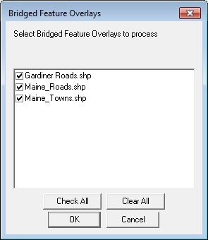
Select Overlays– Click to display the Bridging Feature Overlays dialog shown below. Only the features in the
selected overlays will be processed.All Features – Select to process all features in the specified overlays.
Feature Properties– Select to process only those features in the specified overlays that have the properties defined using the Select Properties button described below.
Select Properties– Click to display the Bridged Feature Identification Properties dialog shown below.
All Features – Select to process all features in the specified overlays.
Bridge Feature Properties
Attribute Name/Value– An attribute with this name and value will be added to the generate bridge features (both the line and optional span points), and can be used to identify as a bridge. Default name “f_code”, default value “AQ040”.
Generate Numeric Bridge ID– If checked, each linear bridge feature created will have an attribute for a unique numerical ID. The attribute name is specified in the Attribute Name box below. Attribute values will be sequential, starting with the value entered in the Start box below.
Generate Bridge Span Points– Check to create span point features for each bridge generated. Span points will be placed at where the bridge intersects the bridged feature. Check the Generate Corresponding Numeric Bridge ID below to give the span point features an ID attribute, with the same name and value as the corresponding line feature.
Buffer Length– The generated bridge features will extend past the bridged feature this distance. The length may be specified in Meters or International Feet.
Default Bridge Length– Bridges crossing linear features will have a total length equal to the width of the bridged feature, plus the buffer lengths. If the bridged feature does not have a width defined, the bridge will be assigned the default length specified here, plus the buffers. The width of the bridged feature will be taken from an attribute with the name specified in the Attribute box to the right, if it exists. These settings only apply to linear bridged features.
Default Bridge Width– The bridge line feature will be given an attribute to specify its width. The width will be equal to the width of the bridging feature it is attached to. If the bridging feature does not have a width attribute, the bridge will be assigned the default width specified here. The width of the bridging feature will be taken from an attribute with the name specified in the Attribute box to the right, if it exists. The width attribute created for the bridge feature will have the same name.
This dialog (below) will be displayed when the Select
Overlays button for either the Bridging or Bridged Feature Properties
group is clicked. All of the active overlays (selected in the Overlay
Control Center) will be listed. This option is useful when features are
sorted by type into separate overlays.
Bridged/Bridging
Feature Identification Properties
This dialog (below) will be displayed
when the Select Properties
button for either the Bridging or Bridged Feature Properties group is
clicked.
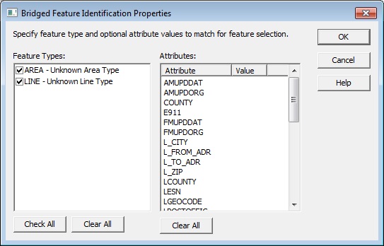
All of the Global Mapper features types present in the selected overlays
are listed on the left. For convenience, area and line features types
are listed together, and given the 'AREA' and 'LINE' prefix respectively.
Select one or more feature types to process.
You
may, if necessary, further restrict the features processed by specifying
one or more attributes. To be processed, a feature must have all of the
attributes values specified on the right (in addition to the type specified
on the left). Note, the list of attributes includes all of the attributes
defined by the features with the types specified to the left. (The list
of attributes may change when the types selections are changed.) A given
feature may not necessarily have all of the attributes listed to the right.
Many settings will be persisted in the registry of the local machine. These
settings will become the default settings the next time the dialog is
displayed.
When
the process is complete, a message box will be displayed giving the number
of bridges generated.
The Create
truncated bridge if bridging feature too short option,
if selected, will place bridge end points at bridging feature end point
if that point is inside the buffer region. A warning will be logged when
this is done. If unchecked, the bridge will not be created and an error
will be logged.
If an error or warning occur during the bridge generation process, a message box will inform you of the name and location of log file. This file is a CSV file that may be loaded to overlay points at the error/warning locations. The layer may be split by “LEVEL” attribute (will have “ERROR” and “WARNING” values).