 3D View
The 3D View in Global
Mapper allows registered users to view gridded elevation data and
any overlying raster or vector data in a true perspective 3D manner. In
addition, any vector data with associated
elevation values can also be displayed in true 3D, and videos may be created
using the Global Mapper Fly-Through feature. The 3D viewer can also display 3D model formats, and render multiple terrain layers in a stack.
To open the 3D view, select the 3D view button from the Viewer toolbar, or select 3D View... from the View menu.
When selected, the 3D View button displays a window containing a 3D view of the data in the current workspace. The 3D view can show in its own window or be docked inside of the main application. For more information, see Window Docking.
Any imagery or vector data being drawn on top of the elevation grid(s) in the main Global Mapper view will automatically be draped on top of the elevation data in the 3D View window. If so configured, any 3D vector data will be displayed in space as well.
3D Toolbar
The following features and tools are available in the 3D View:
-
Navigation
-


 The 3D view has multiple navigation modes that change how the mouse and keyboard move the camera in relation to the data scene. See Rotating, Moving, and Zooming in the 3D viewer for more information on navigation tools.
 -
 You Are Here
While in Walk Mode, the You Are Here functionality can be enabled to display a red arrow in the 2D workspace indicating your current viewing location within the 3D viewer.
-
-
Display Options
-
The Wire-frame view can be toggled on and off to change between a Wire-frame (TIN) and the full textured solid view of the 3D models, terrain data, and 3D vectors.
-
 Default view
Press the default view button to return to the full data extent at the default orientation (looking north and slightly down on the loaded data).
-
Saved Views
Select a saved view from the drop-down menu or use the Save New View option to bookmark the current camera position as a new saved view for the workspace. The View Management option opens a dialog listing the 3D and 2D Saved Views, allowing the user to manage these lists. This list can also be accessed with the Restore Named View command found in the View menu.
-
This option displays a compass on the map. For more settings, go to 3D View Configuration.
-
This option displays a 3D pivot axis. This axis shows the current center-point of the navigation. The pivot axis constantly updates as the display is zoomed and panned to allow for free movement throughout the data. The longer side of each axis denotes the positive direction. The axis display will display shaded darker when it is behind the visible data. For more settings, go to 3D View Configuration.
Shortcut to toggle on/ off the pivot axis display: P key
-

 Set Camera Parameters
Use this tool to manually change the current camera position with the XYZ location, heading, pitch, and field of view.

When this tool opens it will automatically populate with the parameters for the current camera position and view.
Copy Info - copy the Camera Position information to your clipboard to paste outside of the software to save for future use.
Set as Latitude/Longitude - Set the parameters by describing the location using lat/long.
Select from Map - Allows the user to populate these parameters by pointing to a position in the 2D View.
Use Selected Point - Only applicable when Orbit Mode is enabled, this options use a previously selected vector point feature as the pivot point.
Calculate Camera Angle to Keep Current Pivot - this matins the current camera location for use as the pivot point in place of the Camera Angle settings.
Field of View - can also be changed in the Environment section of the 3D View Configuration menu.
-
-
This button is used to access the 3D View Properties dialog, which contains options to configure the 3D view settings, including the vertical exaggeration, the water display, background color, 3D vector display, as well as the terrain and draped image resolution. For more information see 3D View Configuration
-
To link the 2D and 3D views, select the Link 2D/ 3D views button found on the Global Mapper Viewer Toolbar. This will link the relative panning and zooming of the 3D view when the primary 2D map view is panned or zoomed. The 3D view will also refresh based on any changes to the Control Center, such as loading data, turning on and off layers, or running tools that create new data. The link is turned on by default.
When the link is disabled, the 3D view will not refresh to match changes in the primary 2D map view display until the cursor is over the 3D window. Panning and zooming the 2D view will not change the 3D map display.
Keyboard Shortcut: To refresh the 3D view, use the CTRL+3 or F5 hot keys in the 3D viewer.
-
Feature Selection, Measuring and 3D Digitizing Tools
The Selection and Measure Mode tools allow for the selection of vector features in the 3D viewer, and provide options for measuring distances and areas. Right-click with either of these tools to access additional options and settings.
-
Activating the Digitizer Mode in the 3D View will enable the selection of lidar, point, line, or area features in the 3D View window. To select multiple features at one time (sweep select), enable the Digitizer, then click and drag your cursor over the features of interest in the 3D View. Once you stop this action, your features will appear selected in 3D View and in 2D.
-
Context Menu
The right-click menu will bring up the following Digitizer feature creation and feature editing options in the 3D View.
- EDIT - Edit Selected Feature
- Delete Selected Feature
-
 CLEAR - Clear Current Selection
 - Create Area/ Polygon Features
- Create Line Features
- Create Point/ Text Features
- Advanced Feature
Creation Options
-
Move/ Reshape Feature(s)
- Vertex Editing
- Attribute/ Style Functions
- Crop/ Combine/ Split Functions
- Advanced Selection Options
- Analysis/Measurement
-
- Snap Cursor to Feature
- Center 2D view on selected feature (CTRL+ Home)
Keyboard shortcut: Pressing the D key will enable or disable digitizer mode in the 3D view.
- EDIT - Edit Selected Feature
-
Activating Measure Mode will allow you to left-click in the 3D View to define a line for distance measurement or a polygon for area measurement. Right-clicking will end the line or polygon feature to finish the measurement. In the upper left of the 3D View window measurement values will be displayed, right-click to access the 3D View window's Measure Tool menu.
Note: The Measure tool is linked between 2D and 3D, and selecting either button will enable the tool in both 2D and 3D.
Keyboard shortcut: Pressing the M key will enable or disable measure mode.
-
With snap cursor enabled, the digitizer selection tool, digitizer feature creation, or measure tool will show a point feature indicating the nearest selectable point or vertex if one is nearby.
With snap mode enabled, the cursor point in 3D will change color to indicate what is being snapped to. A green point indicates terrain is snapped; an orange point indicates snapping to the vertex of a vector. For more information, see Create New Feature in 3D with Vertex and Terrain Snapping.
When the snap cursor is not enabled, the selection cursor will change color to red to indicate when a selection is available at the current cursor location.
-
-
 Feature Info Tool With this tool enabled, select a vector feature or pixel in raster data to view additional information on the feature or pixel.
-
The drop-down menu may be used to set a specific sky texture background or to set a solid background (None). The color of the solid background may be specified in the 3D View Properties dialog.
-
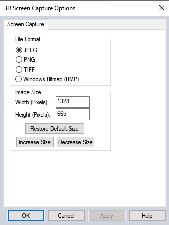
Selecting this tool will bring up the 3D Screen Capture Options dialog (below), used for saving an image of the 3D view to a JPEG, PNG, TIFF, or BMP image format. Additional sizing options are also available.
-
The buttons at the far right corner of the 3D view may be used to make the 3D window full screen when undocked or close the 3D window. Grab the top bar of the 3D view to move and dock or undock the window. For more information about windows, see Window Docking.


 Show
Show 
 2D/ 3D Link

 Snap Cursor

 Vertical Exaggeration

 Water Level


 3D Display and Navigation
| CTRL + 3 | Open or refresh the 3D view | |
| F5 | Refresh the 3D view | |
| Arrow Keys | Pan 3D view left, right, forward, and back or move in. |
|
| Page Up/Down | Zoom out and in* |
|
| Home/ Number 5 / CTRL+SHIFT+D |
Return to default view | |
| CTRL + Home | Center the 2D view on the current selection | |
| Numbers 8 / 2 | Control tilt forward and back * |
|
| Numbers 4 / 6 | Control rotation right and left* |
|
| Numbers 7 / 9 | Move up* |
|
| Numbers 1 / 3 | Move down* |
|
| Mouse Wheel | Roll to zoom in and out or raise and lower the walk mode height. Click and drag to pan | |
| Left Mouse Button | Navigate the view. Forward / back movements tilt the scene up or down; left/right movements rotate the view. * |
|
| Right Mouse Button | Forward / back movements zoom in or out. * | |
 Walk Mode
| Left Mouse Button | Forward / back movements move forwards or back in the scene. Left / right movements rotate the view. | |
| Right Mouse Button | Raise and lower walk mode height. | |
| Mouse Wheel | Click and drag to change the pitch. Roll to raise and lower the walk mode height | |
| Arrow Up / Down | Move into or away from the scene. * | |
| Arrow Left / Right | Rotate the view around the current location. * | |
| Page Up / Down | Raise and lowers walk mode height * | |
Advanced 3D Display and Navigation
| V | Locks movement to the vertical plane | |
| H | Locks movement to the horizontal plane | |
| F11 | Decreases the field of view by 5 degrees* | |
| F12 | Increases the field of view by 5 degrees* | |
| Home /CTRL+SHIFT+D/ 5 key | Default View. This is the standard view that you get when you open the 3D viewer. | |
| Z | Sets the pivot point to the selected feature or, if no feature is selected, the cursor location on the terrain in the 3D view. | |
| Ctrl+Shift+T | Top View. | |
| Ctrl+Shift+U | Bottom View. | |
| Ctrl+Shift+L | Left View. (West) | |
| Ctrl+Shift+R | Right View. (East) | |
| Ctrl+Shift+F | Front View.(South) | |
| Ctrl+Shift+B | Back View. (North) | |
3D Tools and Settings

|
W | Enable or disable wireframe |
|
|
CTRL +W | Enable walk mode |
| CTRL+SHIFT+W | Enable/ disable water level display | |
| T | Enable or disable display of textures on meshes |
|

|
M | Enable or disable Measure tool |

|
D | Enable or disable Digitizer tool |
| CTRL+SHIFT+D | Sets the default view |
|
| E | Resets vertical exaggeration to 1.0 | |

|
CTRL+E | Lower vertical exaggeration |

|
SHIFT+E | Raise vertical exaggeration |

|
P | The P key enables / disables pivot axis display. |
| CTRL+SHFT+P | Enables / disables the path profile display | |
| CTRL+G | Enables / disables display of GPS tracks | |
| Numpad +/- | Raise/ lower water level | |
| CTRL + B | Enables / disables backface culling | |
| CTRL + N | Toggle display of vertex normals for meshes | |
| SIFT+ N | Toggle display of face normals for meshes | |
| N | Toggle normal display mode for meshes (vertex normals and face normals) | |
| CTRL+C | Copy 3D view image to clipboard | |
| CTRL+SHIFT+C | Copy 3D view image to clipboard without notifications |
3D Digitizing and Editing
| CTRL+Z | While digitizing or editing, undoes the last point. | |
| ESC | Clear the current selection, cancel the current digitizing operation, or cancel the current measurement | |
| ENTER | Complete the current digitization operation or measurement. |
|
| DELETE | Delete the selected features. | |
| CTRL+ALT+Left Click and Drag | Sweep deselection to clear the selection of features in the swept area. |
 3D Snapping to types of Features
| P | Hold down when Selecting, Digitizing or Measuring to filter to point features | |
| A | Hold down to filter to area features | |
| L | Hold down to filter to line features | |
| M | Hold down to filter to mesh features |
3D View Keyboard Shortcuts by function
These modes govern how you interact with objects in the view.
- Default Mode: this is the default mode. You can move around the scene, but you cannot interact with objects in the scene.
- Walk Mode: Ctrl+W to enable or disable walk mode.
- Selection Mode: this mode is for selecting one or more objects in the display. Use the ‘D’ key to go to Selection mode.
- Digitizing Mode: this mode is for creating new features. When in Selection mode, use entries on the right-click menu to create new features.
- Measure Mode: this mode is for measuring distances or areas among items in the scene. Use the ‘M’ key to go to Measure mode.
- Snap Mode: this mode governs whether selection or digitization actions are snapped to the nearest geometry vertex. Use the ‘S’ key to toggle this when not in default mode.
There are some predefined views that can help you to navigate in the 3D scene:
- Default View: This is the standard view that you get when you open the 3D viewer. Use the Home key, Ctrl+Shift+D, or the 5 key to go to the default view.
- Top View: This is a view from directly above the scene, looking down. This mimics the top down 2D view orientation. Use Ctrl+Shift+T to go to the Top View.
- Bottom View: This is a view from directly underneath the scene, looking up. Use Ctrl+Shift+U to go to the Bottom View.
- West View: This is a view from the west side (left side) of the scene. This view looks east, showing the West side of 3D objects. Use Ctrl+Shift+L to go to the West View.
- East View: This is a view from the east side (right side) of the scene. This view looks west, and shows the East side of 3D objects. Use Ctrl+Shift+R to go to the East View.
- South View: This is a view from in front of the scene, looking north and showing the south side of 3D data. Use Ctrl+Shift+F to go to the South View.
- North View: This is a view from directly behind the scene, looking south and showing the north side of 3D data. Use Ctrl+Shift+B to go to the North View.
Sometimes it can be useful to restrict the movement of the 3D scene in one dimension or another. You can lock the movement to either a horizontal or vertical plane using the H or V keys. Note: locking is not allowed in Walk mode.
- H: The key enables horizontal locking if it’s disabled; otherwise it disables it. Horizontal locking only allows movement in a plane that’s horizontal to the pivot axis.
- V: The key enables vertical locking if it’s disabled; otherwise it disables it. Vertical locking only allows movement in the plane defined by the screen center and the pivot axis.
3D vector data is exaggerated along with the terrain, so it will align correctly. A bridge going over a gorge with heights of 100 m and 110 m on either end would not match up with the terrain heights of 100 m and 110 m if both weren't exaggerated. If relative elevations of 0 m and 10 m are used with a vertical exaggeration set to 3, those will display at 0 m and 30 m, which would still allow the bridge to match up to the terrain.
The extrusion and altitude mode of 3D Vectors can be controlled globally in the 3D properties, by layer, or for individual features using the modify feature info settings.
Obtain additional control over how 3D vector features are rendered by providing attributes for those features. The supported attributes are as follows:
3D_EX_HT— the value of this attribute will override the default extrusion height and extrude just that height in meters.
3D_ZOFFSET — the value of this attribute allows you to provide an additional offset (in meters) when rendering a 3D vector feature.
EXTRUDE — used to extrude 3D areas down to the ground. If an area has the EXTRUDE attribute with a valid boolean value (YES, Y, TRUE, T, or 1 for enabled, NO, N, FALSE, F, or 0 for disabled), that setting will be used in place of the 3D View Options setting to extrude 3D areas down to the ground.
3D vector data can be rendered with transparency that will be blended as features overlap in the view. Transparency blending is supported for up to eight overlapping features.