The mesh simplification tool will reduce the number of faces or vertices in a mesh by collapsing edges and placing replacement vertices based on the specified method. This will attempt to preserve as much of the shape and boundaries of the mesh as possible, while meeting the requested amount of simplification.
To simplify a mesh, select the mesh feature with the digitizer tool, then navigate to Digitizer menu Move/ Reshape Features and select Simplify Selected Meshes (Reduce Resolution).
Simplification can also be applied to TIN layers. This option is available in the Layer Menu.
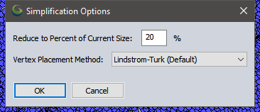
The amount of simplification is controlled by the value in Reduce to Percent of Current Size. For example the default value of 20% would create a new mesh with only 20% or one-fifth the number of vertices. The edges are collapsed in order based on ranking them by how much deviation they would cause in the shape of mesh (the cost of collapsing the edge).
The Vertex Placement Method controls where a new vertex is placed when an edge of the mesh is collapsed. Choose from the following options:
-
Lindstrom-Turk (default) - The new vertex position is calculated by factoring in preserving the shape, preserving the volume, and optimizing the volume and boundary shape. It also preferences equilateral triangles over elongated triangles.
 More information
The replacement vertex position is computed as the solution to a system of 3 linearly-independent linear equality constraints. Each constraint is obtained by minimizing a quadratic objective function subject to the previously computed constraints. There are several possible candidate constraints and each is considered in order of importance. A candidate constraint might be incompatible with the previously accepted constraints, in which case it is rejected and the next constraint is considered. Once 3 constraints have been accepted, the system is solved for the vertex position. The first constraints considered preserve the shape of the surface boundaries (in case the edge profile has boundary edges). The next constraints preserve the total volume of the surface. The next constraints, if needed, optimize the local changes in volume and boundary shape. Lastly, if a constraint is still needed (because the ones previously computed were incompatible), a third (and last) constraint is added to favor equilateral triangles over elongated triangles.
- Lindstrom-Turk (Bounded Normal) - This method is similar to the default, but has an additional constraint that the new vertex placement can not change the face normals by more than 90 degrees.
- Segment Midpoint - The new vertex is placed at the midpoint of the collapsed edge. This is the simplest collapse option and ensures the simplified mesh stays within the original bounds, but is not as good at maintaining volume and shape as Lindstrom-Turk in typical cases. This means the simplified mesh will not exceed the horizontal bounds of the original data extent.
The checkbox option Advanced: Fix Mesh Problems (E.g. Overlap) Before Simplifying will repair the mesh and remove any overlapping segments before simplifying. This should only be used on mesh surfaces representing terrain and meshes that do not have intentional ovelap.
Examples
The below examples demonstrate the effect of simplification looking at a 3D Wire-frame View of a small regular mesh in the 3D viewer. For illustrative purposes, the example mesh is already fairly large face areas, and the mesh simplification performed only reduces to 75% of the original size.
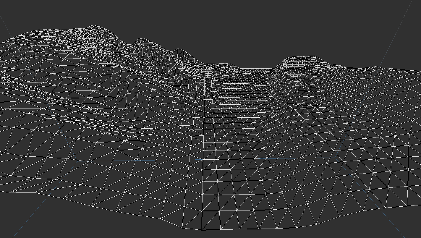
The original mesh was generated from a terrain grid and shows a river feature in the middle with some banks on either side.
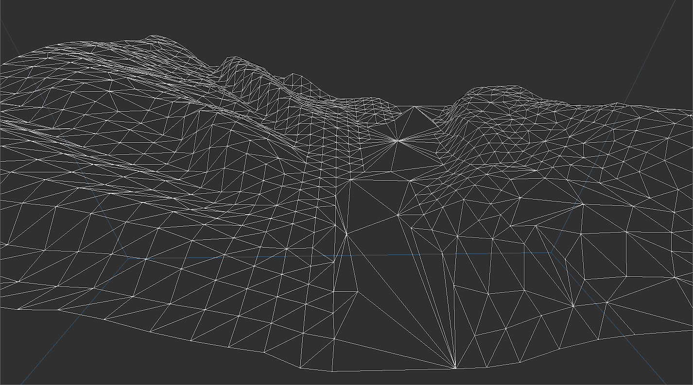
Above is the same mesh simplified to 75% of the original with the Lindstrom-Turk method. The majority of the simplification occurs in the flatter river area, while the more varied banks retain most of the original faces and vertices.

In the above image the same mesh simplification factor was used with the Lindstrom-Turk (Bounded Normal) method. This is almost the same as the previous example since this landscape is fairly flat. There are a few edges in the foreground in the river that were not collapsed based on the additional constraints.

The last example is also set as 75% of the original mesh using the Segment Midpoint method. The removed edges in the middle of the river have been replaced by new vertices in the middle of the two vertices where the edge was collapsed. This is a more straight forward simplification, but is not as optimized for placing vertices to most preserve the original shape and volume of the mesh.
For more information on mesh geometry see Working with 3D Models.