
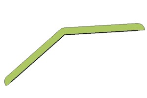
The buffer tool creates an area feature around a select feature or features based on a measured distance away. A buffer can be created from any vector feature (points, lines or areas). There are many applications for buffers, from zonal analysis, boundary or coastal studies, to basic feature creation and editing.
Select the  Create
Buffer Around Selected Feature(s) option from the Digitizer Toolset, or the Digitizer menu, or the context menu under Advanced Feature
Creation.
Create
Buffer Around Selected Feature(s) option from the Digitizer Toolset, or the Digitizer menu, or the context menu under Advanced Feature
Creation.
The Buffer Area Creation Setup dialog (pictured below)
allows for the specification of the number of buffers being created, which sides, and at what distance to space them. A buffer may be applied to one or both sides of a line feature, and multiple
zones can be generated.
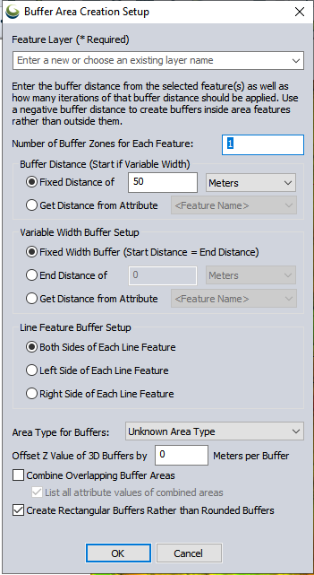
Number of Buffer Zones - specify the number of buffers to generate for each selected feature.
Buffer Distance - specify either a Fixed Distance, or to Get Distance values from the Attribute field of a loaded data layer rather than using a single fixed buffer radius for each feature. Attribute values can also include unit text, like '500 m' or '300 ft' and that will automatically be recognized and used.
To create buffers some distance inside a selected area feature rather than outside of it, simply specify a negative buffer distance.
Buffer distance is measured using Great Circle, Grid, or Rhumb Line distance based on the Calculation Type specified in the Measure/Units section of the Configure Menu. If the Calculation Type is Great Circle, additional vertices may be added to the buffer.
Variable Width Buffer Setup - an attribute may be used to define the start width and another for the end, then the range rings at each vertex would progressively get larger - side segments would go out different distances.
Line Feature Buffer Setup - specify which side(s) of the selected feature to draw the buffer from. Using this option, it is possible to create
a buffer for one side of a selected feature (left or right)as determined from the perspective of the initial vertex.
Area Type for Buffers - specify the Area Style you would like use for the new buffer. Buffers may also be combined, or set to have rectangular or rounded edges.
Combine Overlapping Buffer Areas - combine all overlapping buffers into larger combined areas.
List all attribute values of combined areas - create a comma delimited list of all attribute values for a common attribute in combined area features.
For example, if 2 features have an attribute named 'Water', and values '1' and '2' respectively, the combined buffer will have a single 'Water' attribute with a value '1,2'. If unchecked, the value of the first feature with that attribute will be assigned.
You may also specify offset Z values for 3D buffers in Meters. Additional 3d buffers can be created with the Create Volumetric 3D Mesh Buffer Features tool.
Once the buffer area(s) is have been created, the buffer features will automatically be selected for easy visual identification, access to right-click editing tools, display measurement information, etc.