Create
Watershed
Create
Watershed
The Create Watershed tool allows the user to perform a watershed analysis on loaded terrain data to find stream paths as well as delineate the watershed areas that drain into a given stream section. The watershed calculation uses the eight-direction pour point algorithm (D-8) to calculate the flow direction at each location, along with a bottom-up approach for determining flow direction through flat areas and a custom algorithm for automatically filling depressions in the terrain data.
Perform a watershed analysis by first choosing this option in the Terrain Analysis menu or using the  Create Watershed button from the Analysis Toolbar.
When selected, the command displays the Watershed Generation Options dialog (pictured below) which allows the user to set up the watershed generation process.

The Resolution section controls the resolution at which the loaded terrain data is sampled to perform the watershed analysis. The default values should capture the full resolution of the loaded terrain data. Larger values (i.e. lower resolution) will cause the calculation to be quicker, but less detailed.
The Stream Threshold section controls
how much water must flow to a particular cell before it is considered
part of a "stream". Larger values will result in only more water
flow areas being delineated, while smaller values will cause more minor
water flows to be marked as streams. Each stream segment (i.e. the portion
between and inflow and outflow point) can optionally have the area that
drains directly to that stream segment marked with a watershed area.
Check the Create Watershed Areas Showing Drainage to Streams option to enable creating watershed areas. If you would like to discard any short stream segments that don't have any other streams flowing into them (i.e. short little stub streams feeding into a main trunk), check the option to Discard Stream Starts Less than Some Length. This will remove any short little stream stubs that are below the specified distance threshold (in meters).
Check the Calculate Strahler Stream Order option to generate a STRAHLER attribute containing a value classifying each stream based on the Strahler Stream Order.

The Strahler value is determined through the following:
- If the stream has no children, its Strahler order is 1.
- If the stream has one and only one tributary with Strahler of i, and all other tributaries have an order less than i, then the stream's order is i.
- If the stream has two or more tributaries with a maximum Strahler order of i, then the Strahler order of the stream is i + 1.
Check the Automatically Style Lines to Highlight Flow option to style the generated line features based on multiples of Stream Cell Count. The line style is derived from Stream Line Type.
Depression Fill Depth
Many terrain data sets will contain depressions in the data where flow would terminate unless allowed to fill the depression and spill into the surrounding terrain. The Depression Fill Depth section controls how deep of a depression will be filled before it is considered a basin and flow is allowed to terminate there. The depression fill depth value will automatically be filled in with some guess at a good value based on the range of loaded elevation values, but you might want to modify this, especially if you have relatively flat terrain with a lot of depressions. Note that it can take a while to fill particularly deep depressions. When trying to determine a good value to use for the depression fill depth, consider how high of an embankment or 'dam' the flow might encounter that you want to allow water to fill up to the top of and pour over, or also how deep of a small pond or puddle to fill and allow spilling out of. You can also check the option to Save DEM to Global Mapper Grid File After Filling Depressions to save the depression-filled terrain to a GMG file so you can load that for future watershed operations to avoid having to fill depressions again.
Obstructions from Vector Data (i.e. buildings / culverts)
Use Vector Features to Modify Flow
Check this option to indicate that elevation values in loaded vector data should be considered when performing the watershed analysis. This allows you to use things like buildings, culverts, dams, etc. to block or modify the flow, creating a more realistic watershed.
Only Consider Vector Features with Elevations
Check this option to specify that only vector features with elevations will be considered as obstructions. If unchecked, all features, including 2D features, will be used as obstructions. Any 2D features that are used will act as no-flow obstructions.
Obstruction Features Always Block Flow
Check this option to specify that no flow can go from outside a feature, to inside. This applies to any locations within an obstruction area, or immediately adjacent to an obstruction line, regardless of the height of the feature.
Heights of Vector Features Relative to Ground
Specifies whether the elevation values stored with vector features are relative to the ground, or relative to mean sea level. Typically heights for vector features are specified relative to the ground. If any area features are included and their heights are relative to the ground, the obstruction heights within those areas will be increased by the specified amount. Any features that have an explicit altitude mode set for the feature or layer will obey that over this settings.
Operations at Selected Locations
Perform additional flow and drainage network delineation
based on line and point features selected in the Digitizer
Tool. The Create Watershed Areas
Showing Drainage to Selected Line(s) option will calculate a drainage
(watershed) area for each selected line feature showing which portion
of the loaded terrain drains to the immediate vicinity (within the specified
flow threshold) of the selected line. This is useful to see what drains
to something like a road feature.
Create Watershed Areas Showing Drainage to Selected Point(s)
Calculates a drainage (watershed)
area for each selected point feature to show which portion of the loaded
terrain drains to the immediate vicinity (i.e. within the specified flow
threshold of the point location) of the selected point.
Trace Flow from Selected Point(s) (Water Drop Analysis)
Creates a separate arrowed line starting at each selected point feature showing where a drop of water placed at that point location will flow to.
Trace Flow from Selected Line(s)
Creates an area feature
showing all areas that a particular line feature will
drain to. This is useful for determining something like where a leak from
a pipeline might leak to.
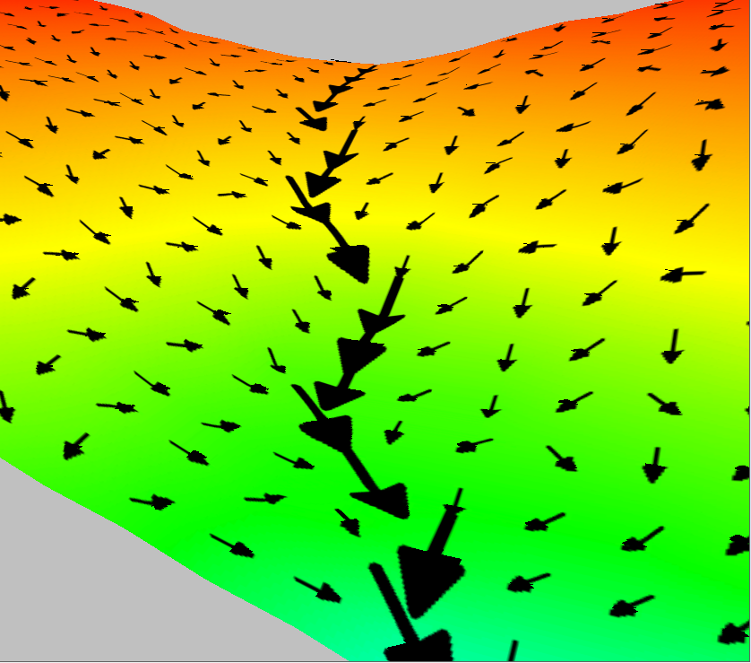
Flow Direction Point Creation
Creates
a point feature (example from 3D viewer below) with the direction (FLOW_ANGLE) and
magnitude (FLOW_ACCUM -the count of cells flowing to a given cell) attributes at each point, then enabling the layer point style
for the quiver plot. The display of the quiver plot is not visible until
zoomed in far enough for decluttering purposes.
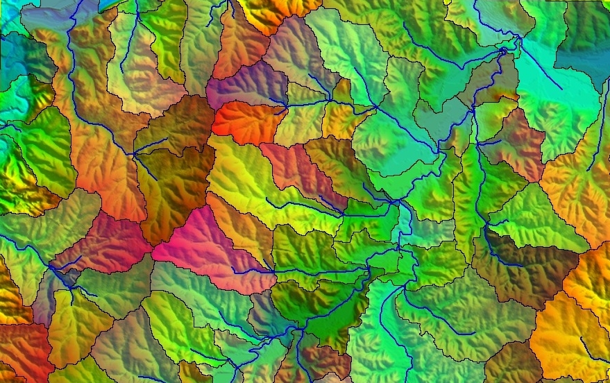
The example below shows a watershed created from a collection of USGS DEMs. In it you can clearly see the stream network as well as the drainage areas for each stream segment.