 Create 3D Model from Selected Lidar Points
The Create 3D Model from Selected Lidar Points tool turns a set of selected point cloud points into a mesh surface that is colorized based on the point RGB values. This tool does a triangulation of the points, and calculation of their normals (orientation) to build a 3D model from the selected area.
This tool requires a Lidar Module license.
To create a mesh surface from points, first select a set of point cloud points using the digitizer tool.
Choose this option from the Lidar Module toolbar, or right-click to Advanced Feature Creation Options > Create 3D Model from Selected Lidar Points.
This brings up the Create Surface Options dialog, pictured below.
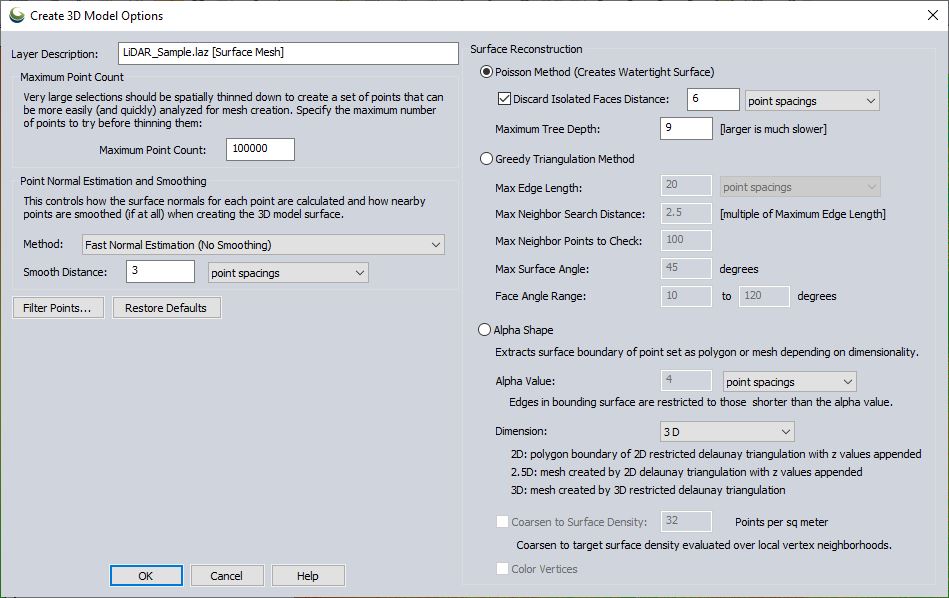
Maximum Point Count
Specify the maximum number of points to attempt to mesh. The tool will perform 3D thinning on the point cloud if the selection is larger than the maximum. This allows for mesh generation of larger sections of point clouds.
Point Normal Estimation and Smoothing
Before calculating a mesh surface, the tool needs to calculate which direction the points are facing, i.e. what represents the "outside" or "front-side" of the surface.
Method
Specify whether to perform smoothing when calculating the direction that the points are facing. Smoothing gets rid of smaller errors in points, and correct errors where multiple results do not line up perfectly. Choose from the following options:
- Fast Normal Estimation (No Smoothing) - The normal will be calculated for each point in the cloud.
- Moving Least Squares (No Polynomial Fit) - Smoothing performed without polynomial fitting is a faster method. This calculates an approximation of the underlying surface based on a weighted neighborhood. This helps calculate the normals that orient the points and resultant faces correctly.
- Moving Least Squares (Polynomial Fit) - A polynomial moving least squares smoothing can help fill in some areas with sparse points. This method takes longer. It fits a plane to the local surface using a polynomial function. This creates a smoother approximation than with no polynomials.
Smooth Distance
Specify the distance to use when smoothing in normal estimation. This is the neighborhood size for the moving least squares smoothing.
Poisson Method (Creates Watertight Surface)
The poisson method is the recommended method for surface generation in most cases, as it creates a more complete surface (i.e. watertight).
Discard Isolated Faces Distance
Check this option and specify a distance threshold to remove surface sections that are disconnected from anything else based on the specified distance threshold.
Maximum Tree Depth
This setting controls how detailed the surface can be. A higher number performs more 3D subdivision (binning) of the data during the mesh calculation. This produces tighter sampling, and a more detailed mesh, but can take longer to process.
A value of 9 will sample 512 grid bins in each dimension (2^9). A value of 11 would sample 2048 (2^11) grid bins in each dimension, producing a more detailed mesh, but taking longer to process. Acceptable values are between 4 and 14.
Greedy Triangulation Method
The Greedy Method grows a mesh by connecting points. It works best on point clouds that are locally smooth (have little local noise) and smooth transition between sections with different densities. With more standard point clouds it is recommended to perform some noise removal and also specify a smoothing method in the Point Normal Estimation and Smoothing section to produce a better mesh result.
Max Edge Length
Specify the largest length allowed in a triangle. This can be defined as a multiple of the average point spacings of the cloud or in linear units (feet, meters). When triangulating the neighborhood of points, if the triangle edge would be larger than the maximum edge length value, then rather than creating that triangle there will instead by a hole in the mesh.
This is necessary so that for example, the foliage of a tree does not connect to the ground. However if the point cloud has areas of low density coverage, too small of an edge length could create holes in the mesh where there should be a surface.
Max Neighbor Search Distance
Specify the maximum distance for a point to be considered part of the local neighborhood during triangulation.
Max Neighbor Points to Check
Specify how many points to check in the neighborhood during triangulation. Typical values are in the range of 50 - 100, but numbers between 4 and 10,000 are acceptable.
Max Surface Angle
In cases where there are sharp edges or corners and where two sides of a surface run very close to each other, there can be issues in the surface. To remedy this, points are not connected if their normals deviate more than the specified angle. Acceptable values are between 0.1 and 179.9 .
Face Angle Range
Specify the minimum and maximum angles in each triangle of the mesh. Typical values are between 10 and 120 degrees.