
Access the Line of Sight analysis by pressing the Line of Sight...
button at the top of the path profile window, or by selecting the option from the Path Profile Calculate menu.
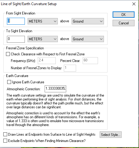
This brings up the Setup Line of Sight/Earth Curvature dialog (pictured below), which allows the user to configure a line of sight calculation along the selected path.
Line of sight analysis can only be performed on a line made up of two points in the path profile (e.g. line of sight analysis cannot be performed on multi-segment paths).
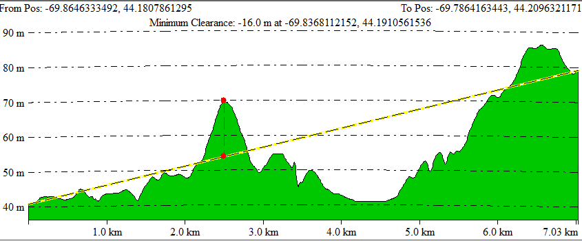
After setting up the line of sight calculation in the dialog and pressing the OK button, the line of sight will be displayed in the path profile window (pictured below). Along with the yellow line depicting the actual line of sight, the point of minimum clearance along the line will be displayed with a dashed red line in the path profile window. The coordinates and height of clearance will also be indicated on the top of the profile window.
Minimum clearance indicates the point of smallest distance between the line and the terrain surface. Then the minimum clearance number is negative, the line of sight is (most) obstructed at the location of minimum clearance, as in the example image below.
For additional statistics on the line and the clearance, go to Path Setup > Show Path Details...
From/ To Sight Elevation
The From Sight Elevation specifies the height at the start position (left side of graph) to use in the line of sight calculations. This height can be entered in either feet or meters, above the ground,above sea level, or above a selected layer. The To Sight Elevation section provides the same functionality for the end position (right side of graph).
Fresnel Zone Specification
When Fresnel Zone![]() Fresnel Zones model the signal loss based on reflection and diffraction. This is an elliptical shape between the transmitter and the receiver. Global Mapper can model the bottom part of the ellipse representing a Fresnel Zone in the Line of Sight and Viewshed tools. Specification is enabled, the analysis will check that a certain
portion (the Percent Clear value) of the first Fresnel zone is clear for a transmission
of a particular frequency. The typical standard is that good
visibility requires that at least 60% of the first Fresnel
zone be clear of obstructions. When enabled, the specified percentage of the first
Fresnel zone will be drawn on the line of sight analysis dialog as a dotted
line, underneath the straight sight line.
Fresnel Zones model the signal loss based on reflection and diffraction. This is an elliptical shape between the transmitter and the receiver. Global Mapper can model the bottom part of the ellipse representing a Fresnel Zone in the Line of Sight and Viewshed tools. Specification is enabled, the analysis will check that a certain
portion (the Percent Clear value) of the first Fresnel zone is clear for a transmission
of a particular frequency. The typical standard is that good
visibility requires that at least 60% of the first Fresnel
zone be clear of obstructions. When enabled, the specified percentage of the first
Fresnel zone will be drawn on the line of sight analysis dialog as a dotted
line, underneath the straight sight line.
Example
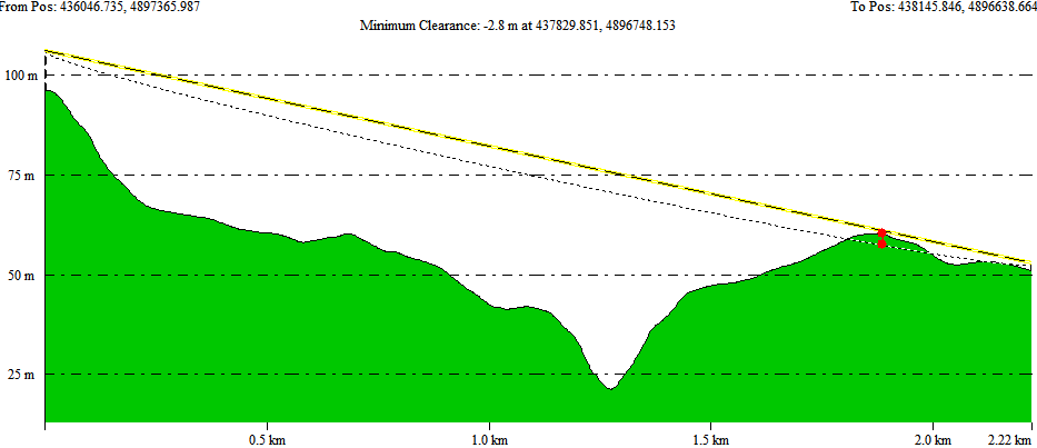
In this example, the line of sight is blocked because there is an obstruction within the specified Fresnel Zone. The Fresnel Zone is shown in the dotted line, and the straight line path is shown in yellow line above it.
Earth Curvature
The Earth Curvature section allows the user to specify if they want to take the curvature of the earth into account when performing the line of sight calculation. In addition, when earth curvature is being used, users can specify an atmospheric correction value to be used as well. The atmospheric correction value is useful when determining the line of sight for transmitting waves whose path is affected by the atmosphere. For example, when modeling microwave transmissions, a value of 1.333 is typically used to emulate how microwaves are refracted by the atmosphere.
Example
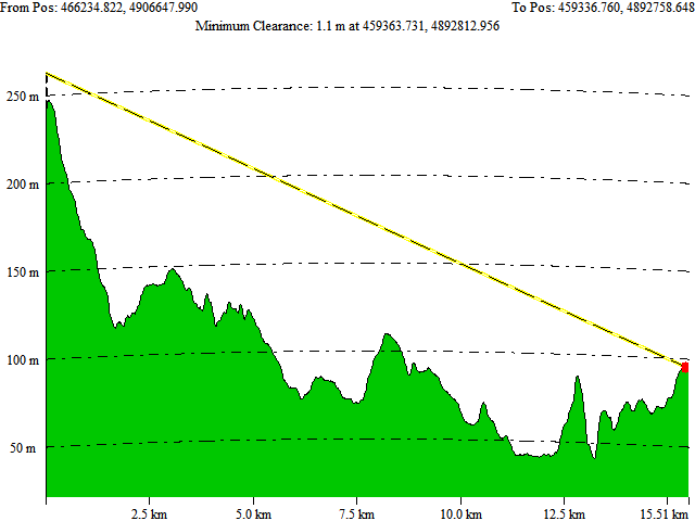
With earth curvature enabled, the profile lines and path will curve to mimic the curvature of the earth. Note that this curvature is exaggerated based on the vertical exaggeration of the elevation scale on the graph. Use the Path Profile Settings to specify an exact scale factor to match elevation scale to distance scale.
Additional
Selecting the Exclude Endpoints when Finding Minimum Clearance options causes the first and last 5% of the elevations along the profile to be ignored when locating the minimum clearance point.