 Automatic Point Cloud Analysis Tool
Find the  Automatic Point Cloud Analysis tool in the Classification dropdown from the Lidar toolbar.
|
|
This tool requires Global Mapper Pro |
The Automatic Point Cloud Analysis Tool is the hub of point cloud classification, segmentation, and extraction tools in Global Mapper Pro. From this tool, you can choose which layers are to be operated on, filter or limit processing, and handle feature models for classification. As with other editing tools in Global Mapper, the original point cloud files will not be edited, but changes to the files will be saved in the workspace or preserved in export of the Lidar data once classified.
In this tool, functions and settings are built into separate sections:

Input Configuration
- Input Layer - Choose which loaded layers will be operated on.
- Selected Only- Only the points currently selected in the workspace by the digitizer tool will be operated on.
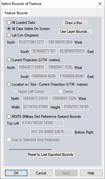
- Specify Bounds... - Set the bounds for the classification by drawing a box on the workspace, by using coordinate extents, or by cropping to a selected area feature. When classifying a large dataset, it is recommended to test the classification on a sample area. Run the classifications multiple times on the sample area, adjusting to values, to obtain a good classification result prior to processing the entire data extent.
- Filter Points... - Contains additional settings for filtering points for classification by elevation and color values, Source ID, and existing classification. The user may also exclude all points outside of a specified scan angle.
Classification and Extraction Shared Settings
Resolution - The resolution at which to analyze the point cloud. This distance, specified in linear units or a multiple of the layer point spacing, will determine the local neighborhood size used for any given point when completing this analysis unless there is a specific overriding parameter for the method. For example, resolution is not used by the Grid MCC ground classification, the smoothing SVM pole classification, or the powerlines classification. These have their own algorithm specific bin size/resolution.
Classification
The classification of points can provide valuable intelligence to a point cloud. These built in tools are designed to identify features in point clouds based on attributes and structures in the point cloud that typically match a type of structure, such as ground, building, etc.
Use the available settings to tailor the tools to best fit your point cloud and the structure of the features you are looking to classify. The majority of settings will be available in the classification section, and a few additional options are also available in the corresponding section of the Classification and Extraction Shared Settings section. Some classification tools have multiple method options as well.
Multiple classifications can be selected at the same time to automatically run one after another. Chosen classifications will be run in a specific order: noise, ground, building, vegetation, powerline, then pole.
Automatic Ground Classification - Prerequisite for all other classifications.
Building Classification - Identifies buildings and flat plane features.
Powerline Classification - Identifies cable/line features.
Vegetation Classification - - Identifies vegetation points, with optional distinctions in tree height.
Pole Classification - Identifies cylindrical pole-like objects.
Noise Classification- Removing outlying noise points from a cloud improves the quality of the cloud and the accuracy of all other classifications.
Enable Report
Enable this option to see a report of the classification results and to save the classification settings as a .json file for future use or to share with other users. The Enable Report option generates a report that summarizes the settings used and the results of a classification method. The report is generated as a text file in a Reports folder at the specified location.
To load the saved settings .json file: Open the automated Point Cloud Analysis tool, check the box to Enable Custom Feature Models, then from the list of options that appear, choose Load Models.
Advanced options
Geometric Segmentation - Identifies features in the point cloud based on user chosen attributes and thresholds. A dynamic and hands on method for Lidar classification.
Use Custom Segmentation Parameters - check this box to further tailor the segmentation based Automatic Classification methods (Max Likelihood) using the setting currently chosen in the Geometric Segmentation tool.
For example, when classifying ground points with the Max Likelihood method, you can open the Geometric segmentation tool and change the curvature value to better match the data's terrain.
Extraction
Features to Extract - Extracts point, line and area features from classified point clouds.
Flags to Apply
Model Key-Point Identification - Find and apply a flag to model key-points required for generating a TIN surface.
About Point Cloud Classification
Global Mapper's Lidar auto-classification tools allow you to identify and classify noise, ground and non-ground points from unclassified point clouds. When you run auto classifications on multiple input files, the same classification parameters are applied to each input file. If ground conditions and quality of Lidar points vary by file, then files should be classified separately. The accuracy of auto-classification results will depend on the level of detail and the quality of point cloud data, in addition to the operator's knowledge of ground/terrain conditions. Post-processing and Quality Assurance steps can be used to optimize classification settings when defaults do not yield satisfactory results. Global Mapper's Path/Profile tool has an available Lidar Toolbar, so that manual classification of points in a profile view may be conducted.
Outlying elevation values can lead to spurious or inaccurate classification results. Laser pulse returns from obstructions such as haze, air craft, or birds or multiple reflections from tree canopies can result in outlying points with very high elevation values. Ground structures and trees or tree canopies can create multiple reflections, leading to excessively long travel times back to the Lidar sensor and creating points with outlying low elevation values. These points with anomalous high and low elevation values are noise points, and can be most easily and quickly seen by coloring or drawing point clouds by elevation. The noise points will expand the expected elevation range for the area. If your Lidar data has noise points, and you plan on using the Auto-Classify Ground Points and Auto-Classify Non-Ground Points tools, you will want to Auto-Classify Noise points first. You can also filter out extreme spikes by using the option to Delete Samples Over X Standard Deviations from the Mean in the Lidar Load Options menu.
Most Lidar data will contain a certain percentage of ground points, along with a number that are unclassified. The Auto-Classification Ground Points tool can be used to identify previously unclassified ground points for use in eliminating unclassified points as possible building or tree features, or for employing in the creation of a digital terrain model. Once ground points have been classified a different algorithm may be employed to identify previously unclassified non-ground features, such as buildings, trees, and powerlines by using the Auto-Classify Non-Ground Points. In the classification of non-ground points, relatively flat surfaces that are above the height determined to be ground height will be classified as buildings and those that are vertically offset from neighboring points by user-defined parameters will be classified as trees or powerlines.
The typical workflow for auto-classification of unclassified Lidar points is to classify noise points, ground points, and then non-ground points. Identifying previously unclassified noise points will improve the ground auto-classification results, and classifying previously unclassified ground points will improve the auto-classification of non-ground points. Some of the classification dialogs and will allow for user defined bin size settings, the bin size you want to set is based on the resolution of your Lidar data.