Point Database Preferences
To access the Point Database Preferences, click Options > Preferences, and then select the Point Database tab. This selection will allow you to alter a number of settings related to how Point Database Conversions are performed as well as point style information for converting point database files to AutoCAD formats.
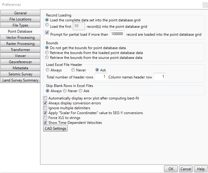
Record Loading
The Record Loading region allows you to control various features related to loading large point database files.
- Load the complete data set into the point database grid may be selected if you wish to always completely load the data. Note that this means large data sets may take longer to load.
- Load the first # record(s) into the point database grid may be selected if you always wish to load only a subset of the data. This will improve loading speed for large data sets.
- You may additionally check the Prompt for a partial load if more than # records are loaded into the point database grid if you wish to be alerted for particularly large data sets, which may take longer to load.
- Note that in all cases, a partial load only affects the data display. When the job is processed, all rows will be converted, even if they are not displayed in the partial load.
Bounds
The Bounds field allows the user to select how the bounding rectangle for a Point Database job is determined.
- Do not get the bounds for point database data may be selected if no bounds are to be used.
- Retrieve the bounds from the loaded point database data will use the Minimum Bounding Rectangle of the loaded (if database is partially loaded) data to define the Bounds.
- Retrieve the bounds from the source point database data will use the Minimum Bounding Rectangle of the source data to define the Bounds.
Excel
The Load Excel File Header region allows you to control various features related to input Excel files that may or may not include header rows (for example, rows containing column names, or other rows with no point data).
- If you know that you will always be importing Excel data containing a header, you may select Always.
- If you know that you will always be importing Excel data containing a header, you may select Never.
- Otherwise, select Ask so that users will be prompted each time.
- If you always expect to have a header of a certain size, enter the number of header rows in Total number of header rows.
- If you always expect the column names to be in a specific row, you may provide it in Column Names Header Row.
The Skip Blank Rows in Excel Files region allows you to control how the Point Database job handles blank rows in input Excel files.
- If you know that you will always want to skip blank rows in Excel files, you may select Always.
- If you know that you will never want to skip blank rows in Excel files, you may select Never.
- Otherwise, select Ask so that users will be prompted each time.
Other Options
If the Automatically display error plot after computing best-fit option is not checked, you will need to manually click the Display Error Plot button to view the error plot once the Best Fit job has been processed.
If the Always display conversion errors option is checked, you will receive warnings on each individual error encountered during processing, with the option to continue or abort. The error dialog, however, does have an option to apply your answer to all subsequent errors. If you do not check this option, and there are errors, you will simply receive a final status of 'Some Rows Encountered Errors.'
If the Ignore multiple delimiters option is checked, repeated delimiters will be skipped when reading in data that is defined with a delimiter. For example, a CSV (comma separated value) file containing "A,B,,,C" would be read in as "A,B,C." If multiple delimiters are used to represent empty columns, this option should not be checked.
Check Show Time Dependent Velocities to enable the HTDP Velocity columns in the Point Database Conversion output table. When this option is selected, the drop-down option for setting columns for North, East, and Up will appear under the Target Coordinate System.
The CAD Settings button will bring up a window with settings to control the DXF/DWG and DGN Point Styles, determining the appearance of the point style that will be used in DXF/DWG output files.
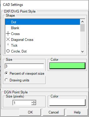
When viewing these output files within AutoCAD, for example, the points should appear with the Shape, Size, and Color specified in this region of the preferences. The DGN Point Style field allows you to control the appearance of the point style that will be used in DXF/DWG output files.