 Point Database Forward Inverse
The Point Database Forward Inverse job can be used to compute either a forward or inverse calculation from a point database.
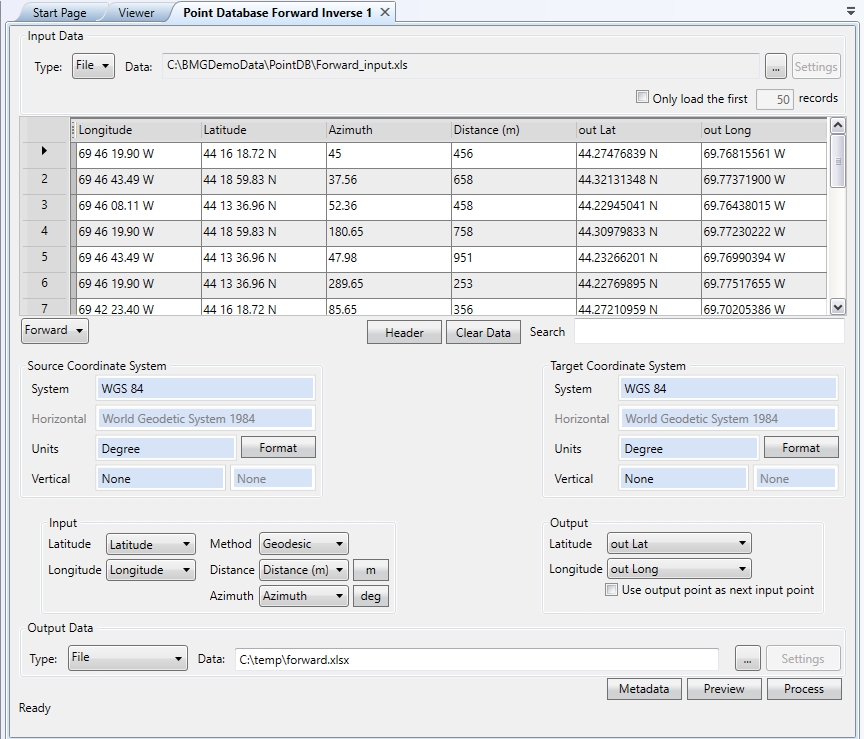
A forward calculation (point database below) is used to compute a new coordinate that is a given distance and azimuth away from a starting coordinate.
The conversion may be calculated using the Geodesic![]() Geodesic distance is the shortest possible line between two points on the surface of the datum. This is also referred to as Great Circle distance.
It is the shortest distance between two points along the surface of the ellipsoid. (Great Circle),
Rhumb Line
Geodesic distance is the shortest possible line between two points on the surface of the datum. This is also referred to as Great Circle distance.
It is the shortest distance between two points along the surface of the ellipsoid. (Great Circle),
Rhumb Line![]() A Rhumb Line is a line of constant bearing. Rhumb line distance measures the distance between two points maintaining a line of constant bearing relative to true north.
Rhumb Lines are frequently used to plot navigation lines. (Constant Azimuth), or Grid
A Rhumb Line is a line of constant bearing. Rhumb line distance measures the distance between two points maintaining a line of constant bearing relative to true north.
Rhumb Lines are frequently used to plot navigation lines. (Constant Azimuth), or Grid ![]() Grid distance measures the distance following a straight line between two points in grid space.methods. To complete a Forward
calculation, you must have:
Grid distance measures the distance following a straight line between two points in grid space.methods. To complete a Forward
calculation, you must have:
- A starting coordinate in a known coordinate system
- A destination coordinate system (on the same Datum as the starting coordinate)
- Distance and Azimuth ahead from the starting coordinate
Note: For both Forward and Inverse conversions, when height values are entered, the distance is scaled to a height above the ellipsoid. For more information see Height Above Ellipsoid (HAE) Calculations
Forward Calculation
To perform a Forward calculation on a point database file you will need to:
-
Create a new Point Database Forward Inverse job by going to File>New>Job>Point Database Forward Inverse. From the drop down menu under the point database preview, select 'Forward'.
-
Load a point database file by clicking the Browse (...) button in the Input Data area at the top of the job window. You can load data into the table from a file, or from an ODBC database connection.
Note: Only extensions that have a defined text file scheme will show as supported files in the Open dialog. The extension of any custom text file scheme that you have defined will appear within the file type filter list. To see files with custom extensions first set up a custom text file scheme. Alternately, type a file name of * in the open dialog, and then press enter to select from all files.
-
Select your Input and Output coordinate systems. Forward calculations require that input and output points be on the same datum.
-
Use the Format buttons to select the display format for your input and output coordinates. This is very important for angular units.
-
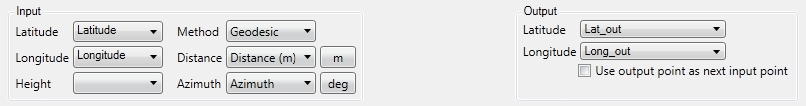
The Forward column setup is split in half with the Input settings on the left side and the Output settings on the right side. In the Input and Output sections, select the columns that contain the input and the columns that will receive the output (or Add New Column for the Output).
The drop down menus will contain the names of the columns in the table. Using the drop down menus, select the column name that relates to the appropriate data type. If the table was loaded with no column names, default names will be used (C1, C2, etc) in the menus. The Calculator will label the drop down menus according to the coordinate systems that have been set in the Point Database Conversion Job. For example, if you are converting geodetic points (Lat/Long), the text boxes will indicate "Geodetic Latitude" and "Geodetic Longitude". For grid (UTM, State Plane, etc) the labels will indicate "Northing" and "Easting" where appropriate. This is true for both the Inputand Outputsides of the dialog.
-
Input Settings
Using Distance and Azimuth:
In order to compute Forward coordinates, the user must specify 3 parameters (Input side only):
Method: Choose the method (Geodesic, Rhumb, or Grid) for the type of distance you are entering from the drop down list.
Note that Grid is only available when using a Projected coordinate reference system.
Distance: Use the drop down box to specify the column containing the Distance values and specify the type of unit the distance values represent.
Azimuth: Use the drop down box to specify the column containing the Azimuth values -
Output Settings:
The output of a Forward calculation is a coordinate point (scale and convergence values are optional output for projected systems). On the Output side of the Conversion Settings window you will need to specify columns in the Point Database Grid for your ending coordinates, or the option to 'Add New Column'.
-
Once you have specified all of the input and output columns, click OK.
-
Click the Calculate button. Values will be read from the input columns for each row in the table, converted, and written to the specified output columns.
Inverse Calculation
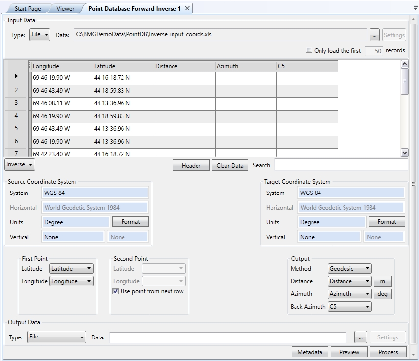
An Inverse Calculations (point database setup below) computes the distance between two known coordinates
on the same datum. The result may be calculated using the Geodesic![]() Geodesic distance is the shortest possible line between two points on the surface of the datum. This is also referred to as Great Circle distance.
It is the shortest distance between two points along the surface of the ellipsoid.,
Rhumb
Geodesic distance is the shortest possible line between two points on the surface of the datum. This is also referred to as Great Circle distance.
It is the shortest distance between two points along the surface of the ellipsoid.,
Rhumb![]() A Rhumb Line is a line of constant bearing. Rhumb line distance measures the distance between two points maintaining a line of constant bearing relative to true north.
Rhumb Lines are frequently used to plot navigation lines., or Grid
A Rhumb Line is a line of constant bearing. Rhumb line distance measures the distance between two points maintaining a line of constant bearing relative to true north.
Rhumb Lines are frequently used to plot navigation lines., or Grid![]() Grid distance measures the distance following a straight line between two points in grid space. method. Both the source and destination points must
be referenced to the same geodetic datum.
Grid distance measures the distance following a straight line between two points in grid space. method. Both the source and destination points must
be referenced to the same geodetic datum.
Note: For both Forward and Inverse conversions, the distance specified is the distance along the surface of the datum. Even if you enter in an elevation value, the distances will be interpreted as being on the datum.This is also true for Geocentric coordinate systems that are 3 dimensional by nature. 3D Cartesian coordinates will be reduced to the surface of the datum.
To perform an Inverse calculation on a point database file you will need to:
-
Create a new Point Database Conversion Job by going to File>New>Point Database Forward Inverse.
-
Select Inverse from the drop-down above the Source Point Coordinate System.
-
Load a point database file by clicking the by clicking the Browse (...) button in the Input Data area at the top of the job window. You can load data into the table from a file, or from an ODBC database connection. Note that the extension of any custom text file scheme that you have defined will appear within the file type filter list.
-
Select your Starting and Ending coordinate systems. Inverse calculations require that both coordinate systems be on the same datum.
-
Use the Format buttons to select the display format for your input and output coordinates. This is very important for angular units.
-
Use the First Point, Second Point, and Output sections to set the columns for input and output. In the Inverse dialog the columns setup is split in half with the Input settings on the left side and the Output settings on the right side.
The drop down menus will contain the names of the columns in the table. Using the drop down menus, select the column name that relates to the appropriate data type. If the table was loaded with no column names, default names will be used (C1, C2, etc) in the menus. The Calculator will label the drop down menus according to the coordinate systems that have been set in the Point Database Conversion Job. For example, if you are converting geodetic points (Lat/Long), the text boxes will indicate "Geodetic Latitude" and "Geodetic Longitude". For grid (UTM, State Plane, etc) the labels will indicate "Northing" and "Easting" where appropriate. This is true for both the Input and Output sides of the dialog.Input
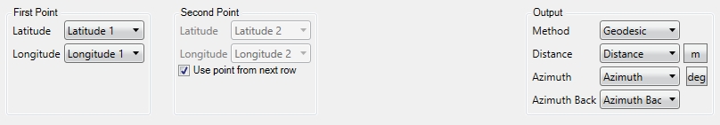
The Input settings include drop down boxes for two columns of coordinates. This is because in order to perform an Inverse calculation, there must be two known points for the calculations. Select the columns containing the starting coordinates and the ending coordinates.
The Use Input Point From Next Row toggle instructs the Calculator to take the value in the next row (row below) and calculate the inverse (as opposed to using values in another column). Example
Output
The Output settings will vary depending on the chosen Method (Geodesic, Rhumb, or Grid). Note that Grid is only available when using a Projected coordinate reference system.
Method - Geodesic, Rhumb, or Grid
The following output columns may be set:
Distance Geodetic/Grid Distance between the 2 points
Azimuth Geodetic/Grid Azimuth Ahead (Point. A to Point. B)
Azimuth Back Geodetic/Grid Azimuth Back (Point B to Point A)You may assign each result to a column using the drop down boxes. Specify (none) if a calculation is not needed. For example, you may only need the Geodetic Distance and Geodetic Azimuth Ahead for a series of points. Using the drop down boxes you would assign those results to their appropriate columns. You would select (none) for the remaining boxes.
-
Click on the appropriate buttons to set the Output Distance Units and Azimuth Units.
-
When all the settings have been filled in, click OK to return to the Point Database Job page.
-
Click Calculate to process the Job. The output will display in the table in the columns selected under Conversion settings.
To create a Batch of the Point Database Forward Inverse job, right-click on the job in the Project Manager and select the Batch Add option.