Performing Point Database Conversions
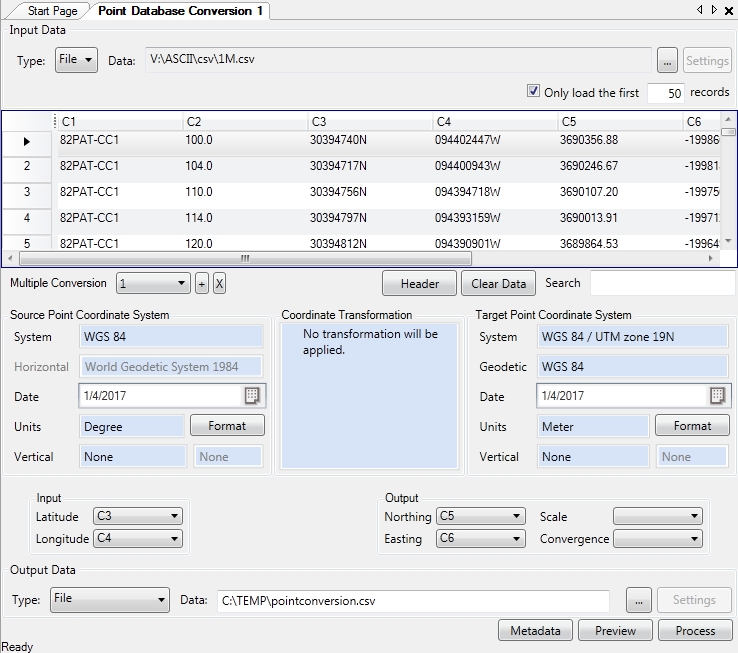
To create a new Point Database Conversion job (below), you can create one from the Start Page:
-
Right-click in the Project Manager and select Create New Job>Point Database Conversion
-
Click on the
button on the tool
bar.
Once you have your new job created:
-
Load a point database file by clicking the "..." button in the Input Data area at the top of the job window. You can load data into the table from a file or from an ODBC database connection.
Note: The extension of any custom text file scheme that you have defined will appear within the file type filter list.
-
Use the Format buttons to select the display format for your input and output coordinates. This is very important for angular units.
-
If you select input and output coordinate systems that are based on different Datums, you will need to select a Coordinate Transformation. If you do not, when you click the Calculate button, you will be prompted to do so.
-
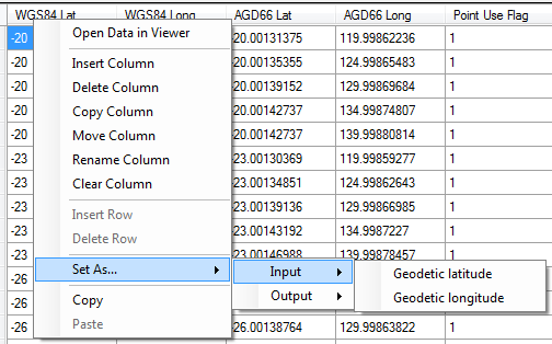
Use the Input section to select the columns that contain the input coordinates and the Output section to select or add the columns that will receive the output.
Alternatively, you can right-click on a column header to make these same assignments:
When performing a NADCON5 transformation, the estimated error calculation (in meters) for individual points can be written to columns in the database output. After choosing a NADCON5 transformation, the drop-down column options become available for N/S Error, E/W Error, and Vertical Error.
-
Choose the Preview button if desired to preview the resulting table.
Note: Preview is not available if the output file is overwriting the input file.
-
Click the Calculate button (calculated example below). Values will be read from the input columns for each row in the table, converted, and written to the specified output columns.
Note: The point database conversion
will load with Conversion 1 by default. If you would like to perform
additional conversions using different columns, use the drop down menu or '+' next in the 'Multiple Conversion' field to add additional conversions. Once an additional conversion is added, Multiple Conversion numbers (1,2, 3...) will populate in the drop-down menu. With a conversion number selected, define the Input and Output coordinate systems and the Input and Output columns for that conversion. All conversions defined will be performed
when the job is processed, with output columns added for each of the defined conversions.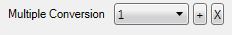
Output Format Special Cases
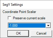
SEG-Y
If you are writing out to the SEG-Y Format there is a settings option to change the scale factor of the data. Press the settings button to change the Coordinate Point Scalar of the output data.
This is for users who wish to have an implied decimal, or otherwise modify the displayed scale of their data. This is sometimes necessary when converting the units output file to properly maintain precision. With the Preserve current scale check-box checked no changes will be made to your data on export.
If you uncheck the option then you will have access to a drop-down menu that allows you to modify the scale of the exported data.
XLS
Note: XLS data may not maintain leading zeros when opened in Excel. When using a coordinate format that requires leading zeros, such as Packed DMS, it is recommended to export to CSV and then open in Excel, so that leading zeros will be maintained.
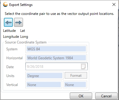
Vector
Output formats that contain vector geometry have additional settings. These settings allow you to confirm which coordinates in the table become the stored geometry. This Export Settings dialog will appear automatically when specifying a vector output including: AutoCAD DWG, AutoCAD DXF, ESRI Shape, MapInfo Interchange, MapInfo Tab, Microstation Design, ESRI ArcInfo Generate, GML, and KML.