Access the Line of Sight analysis by pressing the Line of Sight... button at the top of the path profile window, or by selecting the option from the Path Profile Calculate menu.
This brings up the Setup Line of Sight/Earth Curvature dialog (pictured below), which allows the user to configure a line of sight calculation along the selected path.
Line of sight analysis can only be performed on a line made up of two points in the path profile (e.g. line of sight analysis cannot be performed on multi-segment paths).
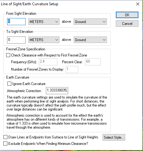
From Sight Elevation and To Sight Elevation can be set to Meters or Feet above Ground, Sea Level or a Selected Layer.
The From Sight Elevation section allows
the user to select the height at the start position (left side of graph)
to use in the line of sight calculations. This height can be specified
in either feet or meters above the ground or above sea level. The To Sight
Elevation section provides the same functionality for the end position
(right side of graph).
The Fresnel Zone Specification section
allows you to have the line of sight analysis also check that a certain
portion (the Percent Clear value) of the first Fresnel zone for a transmission
of a particular frequency is clear. The typical standard is that good
visibility requires that at least 60% (the default) of the first Fresnel
zone for the specified frequency be clear of obstructions. If Fresnel
zone clearance is being selected the specified percentage of the first
Fresnel zone will be drawn on the line of sight analysis dialog as a dotted
line underneath the straight sight line.
The Earth Curvature section allows
the user to specify whether they want to take the curvature of the earth
into account while performing the line of sight calculation. In addition,
when earth curvature is being used, they can specify an atmospheric correction
value to be used. The atmospheric correction value is useful when determining
the line of sight for transmitting waves whose path is affected by the
atmosphere. For example, when modeling microwave transmissions a value
of 1.333 is typically used to emulate how microwaves are refracted by
the atmosphere.
Selecting the Exclude Endpoints when Finding Minimum Clearance options causes the first and last 5% of the elevations along the profile to be ignored when finding the minimum clearance point.
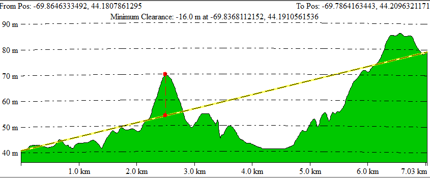
After setting up the line of sight calculation in the dialog and pressing the OK button, the line of sight will be displayed in the path profile window (pictured below). Along with the line depicted the actual line of sight, the position and vertical separation of the minimum clearance of the line of sight will be displayed with a dashed red line in the path profile window.