Changing the Shape of Area and Line Features
You can change the shape of area and line features
in several different ways. You'll first have to enable the Show
Area and Line Vertices option (Shift+V is a keyboard shortcut to toggle
this setting) before having access to the features described below. You'll
also need to select the vertices to work with before performing any of
the described operations except inserting new vertices.
The following options are available for reshaping
area and line features:
Edit
Length of Area and Line Feature Segments
This option allows
you to click on a segment of an area or line feature and be presented
with a dialog showing the length of the segment, which you can then edit.
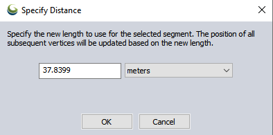
All vertex locations from the end of the segment on to the end of the line
will be adjusted to make the clicked-on segment the specified length.
If you also have the option enabled to label each segment with its length
on the Vector Display tab of
the Configuration dialog then you can just double-click on a segment to
edit its length.
Always
Render Vertices for Selected Features
This option specifies whether
each vertex along area and line features selected with the Digitizer/ Edit
Tool should be displayed. Use this option rather than the Render Area
and Line Vertices option above to only display vertices for features that
you are actively editing in order to prevent excessive clutter on the
map.
 Move Selected Vertices
This
option allows you to move selected vertices to a new location. To do this,
hold down the left mouse button and move the vertices to the desired
location, then release the left mouse button. You can repeat this action continually to refine
the location . Right clicking or pressing the ESC key will
complete the operation. Note that while moving a single vertex, you can
use the Snapping feature to help align the vertex with existing features.
If you'd only like to move the selected vertices either horizontally or
vertically, you can hold down either the 'X' or 'Y' keys on the keyboard
to restrict the movement to that axis. Holding down both keys will move
the vertices diagonally.
Join Selected Vertices
This option allows you to set multiple
vertices to the same location, which ensures that there
are no gaps along the seams of features. Once you've selected this option,
hold down the left mouse button and move the vertices to the new desired
location, then release the left mouse button. Right click or press the
ESC key to complete the operation once you're done. Note that while joining
vertices, you can use the Snapping feature to help align the vertices
with existing features.
Deleted Selected Vertices
This option allows you to delete the
selected vertices.
CTRL+Delete is the hot key for deleting selected vertices.
Set Position of Selected Vertices
This option displays a dialog
allowing you to manually position the selected vertices by entering their
new position in either latitude/longitude coordinates or coordinates in
the currently configured view projection/datum. If the selected vertices
are from a 3D line or area feature, you will also be able to set the elevation
value to use for the vertex.
This option allows you to insert a new
vertex into the selected area or line feature. To insert the vertex, select
the option from either the Move/Reshape
Feature(s) or Vertex Editing Digitizer
(right-click) submenus, or the Digitizer(Edit) toolbar button.
Left-click at the location where you want
the new vertex inserted. The vertex will be inserted on the area or line
feature at the clicked location along the nearest segment of the feature.
Alternately, if you hold down the SHIFT key while left-clicking the new
vertex will be placed on the selected feature(s) at the nearest location
to the click location. You can also use this feature to extend features.
The newly created vertices will be automatically selected. If you need
to add multiple vertices to the selected feature(s), simply hold down
the 'I' key when left-clicking to place the vertex and you will remain
in the insert vertex mode.
Reverse
Order of Vertices in Selected Area(s)/Lines(s)
Reverses the
order of all vertices in a selected line or area feature. This option can be used for data management, but is also useful for Digitizer operations that relate to the beginning or ending or a feature.
Resample
Selected Feature(s) at Specified Spacing
This option is found
under the Move/Reshape Feature(s)
Options submenu and allows you to resample your selected area or line
feature at a specified interval. This is useful if you want to add a lot
of new vertices along your feature to make reprojection work better or
to facilitate smoothing of the feature.
SIMPLIFY (Reduce)
Vertices of Selected Feature(s)
This option will automatically remove vertices that do not
significantly contribute to the shape of your selected area or line features.
This is useful to significantly reduce the size of features without
giving up much detail in the shape. Select Line or Area Features to simplify with the Digitizer tool and
right-click. In the Move/Reshape
Feature(s) submenu, selected the SIMPLIFY - Simplify (Reduce) Vertices
of Selected Line/ Area Feature(s) option. When selected the Enter Simplification Threshold dialog will appear
(pictured below).
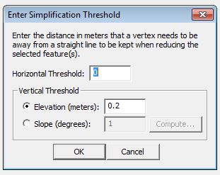
Horizontal Threshold — Use this field to enter the threshold that will be used to simplify
the 2D components of each vector feature. This is the distance in meters
that a vertex needs to be from a straight line in order to be kept in
the feature. Vertices that are this distance or further from the straight
line will be kept. Vertices that are closer than this distance from the
straight line will be discarded.
Vertical
Threshold — This section applies only to 3D data. The threshold specified
here will be applied to the vertex elevations. If the calculation
exceeds the threshold, then the vertex will be kept.
Elevation (meters) — This field to specifies
a threshold for the elevation difference between vertices. If the
elevation difference is greater than or equal to the threshold, the vertex
will be kept.
Slope (degrees) — This field to specifies a
threshold for the slope difference between vertices. Each calculation
involves three points (A, B, and C). If the difference between slope
AC and slope AB exceeds the threshold, and the difference between slope
AC and slope BC exceeds the threshold, then the point will be kept. Specify
this value in degrees. If you need to use a different means to specify
the slope, click on the Compute... button. Global Mapper will display
a dialog that will allow you to enter the value using raw slope (rise
over run) and a "1 in X" designation. The dialog will
then convert this value to degrees and enter it in the Slope field.
Smooth Selected Line/ Area
Feature(s)
This option allows you to modify the position
of the vertices of your selected line and area features to smooth the
appearance. This can be used to give jagged contour lines a better appearance.
Restore Original Shape of the Selected Feature(s)
If after modifying the shape of an area or line feature you decide that
you want to undo the changes and restore the feature to its original shape,
simply select the feature(s) that you want restored and select the Restore
Original Shape from the right-click context menu. See alsoRestore Original Position of the Point
 Insert New Vertex In
Selected Feature(s)
Insert New Vertex In
Selected Feature(s)